

Method for the automatic determination of the geometrical dimensions of a tool having a machining region in worm thread form
- Summary
- Abstract
- Description
- Claims
- Application Information
AI Technical Summary
Benefits of technology
Problems solved by technology
Method used
Image

Examples
Embodiment Construction
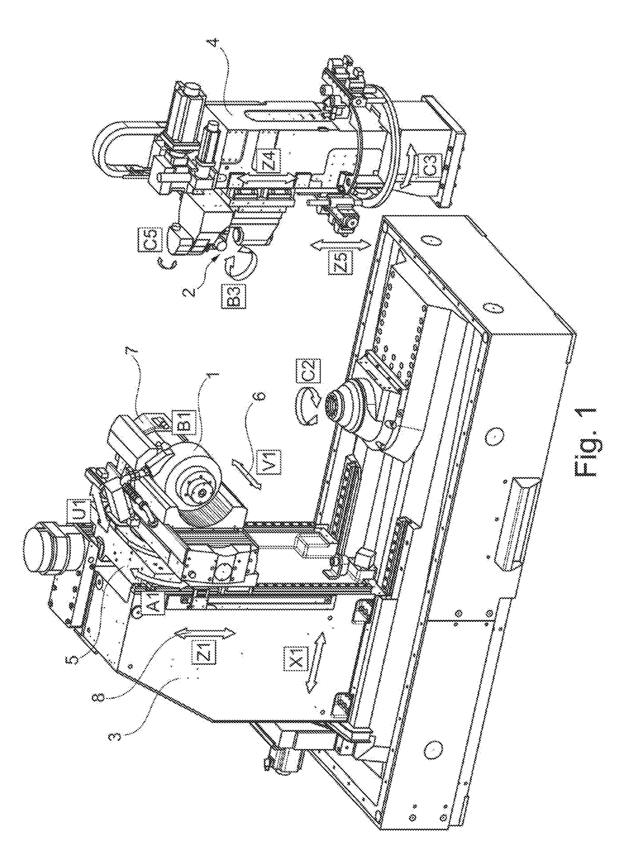
[0055]FIG. 1 shows a grinding apparatus by which the claimed methods can be carried out in principle.
[0056]The axes of a grinding apparatus are drawn in FIG. 1 to improve understanding with respect to the functionality of the grinding apparatus. A machine column 3, and horizontally spaced apart therefrom, a counter-column 4 are shown in the left hand region of the gear cutting machine. A machining head 5 having a shift axis 6 (V1 axis) and a drive motor 7 for receiving a grinding tool 1 can be traveled vertically in the direction of a Z axis 8 along the machine column 3. An installation location 2 of the measurement unit provided in accordance with the present disclosure can lie in the region of the counter-column 4 of the gear cutting machine known per se.
[0057]If a dresser is used as the measurement unit, it is arranged in the region of reference numeral 2 and can inter alia be rotated about the axis B3. A different embodiment of the measurement unit can, however, also be arranged...
PUM
 Abstract
Description
Claims
Application Information