Emergency brake assist system for a vehicle

Inactive Publication Date: 2018-07-05
CONTI TEMIC MICROELECTRONIC GMBH
0 Cites 0 Cited by

AI-Extracted Technical Summary

Problems solved by technology

However, the performance of emergency braking is always...

Benefits of technology

[0010]It may be more advantageous for the time of emergency braking to be brought forward, so as to have more time for decelerating the vehicle. Harm to other road users is ultimately ruled out by the object identification in the region to the rear.
[0011]In a further exemplary configuration, object detection in the region behind the vehi...

Abstract

An improved emergency braking assist system for a vehicle takes account of the region to the rear when specifying emergency braking parameters. The region to the rear is also monitored and the emergency braking parameters optionally adapted during the emergency braking operation.

Application Domain

Technology Topic

Automotive engineeringEmergency brake assist +1

Image

  • Emergency brake assist system for a vehicle
  • Emergency brake assist system for a vehicle
  • Emergency brake assist system for a vehicle

Examples

  • Experimental program(1)

Example

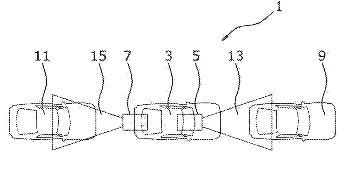
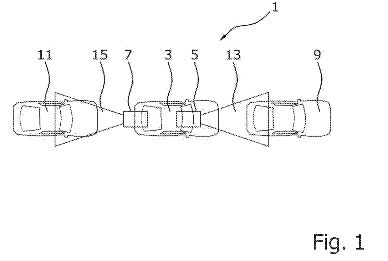
[0026]FIG. 1 shows a traffic situation 1 with a plurality of vehicles 3, 9, 11. The middle vehicle 3 is provided with object detection units 5, 7 for both the region in front of 13 and behind 15 the vehicle 3. The respective object detection unit detects objects in front of 13 and behind 15 the vehicle 3, if objects 9, 11, or vehicles are located in these regions.
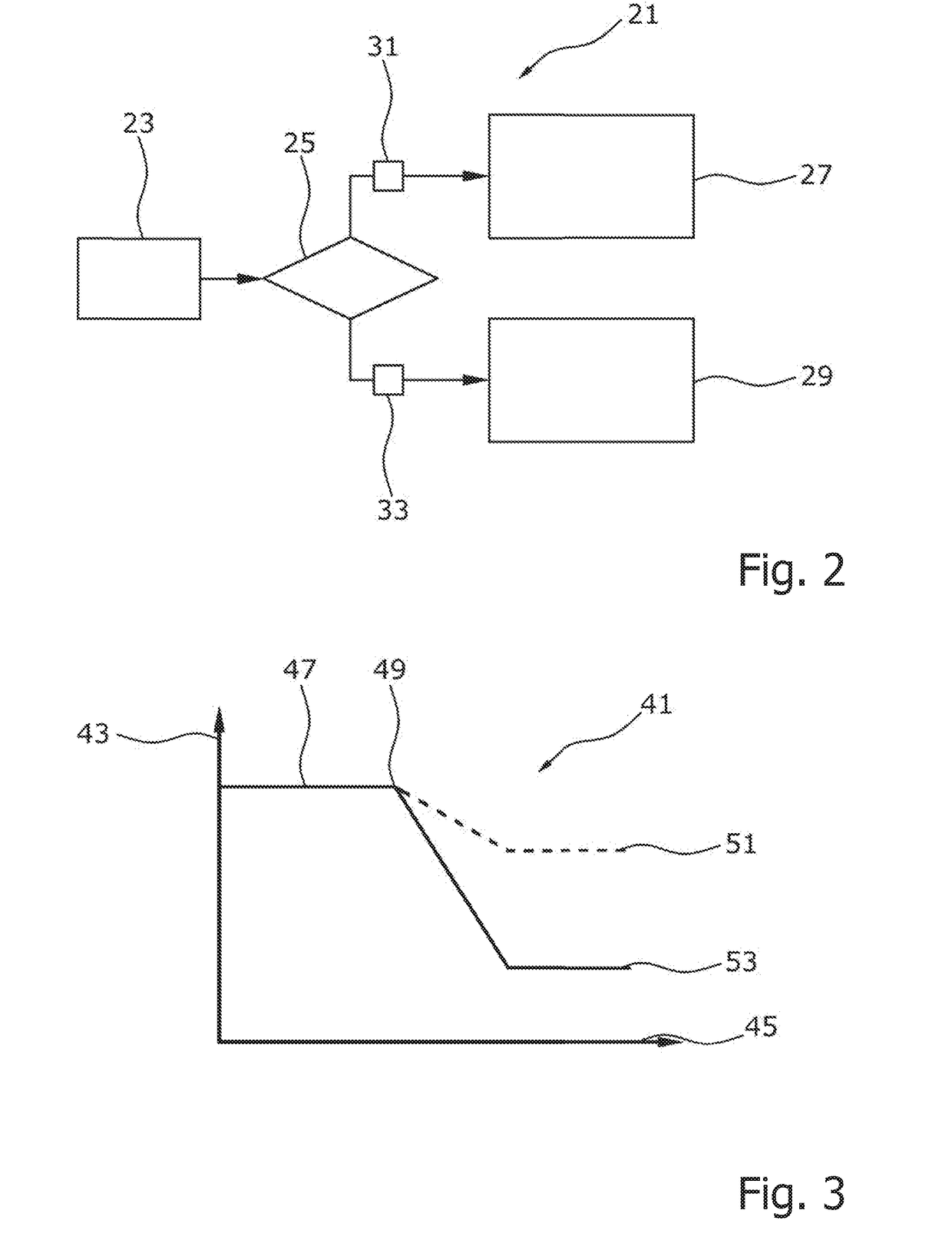
[0027]FIG. 2 shows a flow diagram for operation 21 of an emergency braking assist system. The object detection unit 23 monitors the region to the rear of the vehicle and looks for objects in this region 25. If objects are identified 31, the specified basic parameters 27 are used as emergency braking parameters for the emergency braking. If, on the other hand, no objects are identified 33 in the region 25 to the rear, any emergency braking that is initiated is carried out with optimum parameters 29, parameters which are optimally increased compared with the basic parameters, as the emergency braking parameters.
[0028]The method shown in FIG. 2 for operation 21 of the emergency braking assist system is also carried out during emergency braking which is already taking place. Should the object detection unit 23 identify 31 an object in the region 25 to the rear after the emergency braking operation has begun, the emergency braking is continued with the basic parameters 27. The increased optimum parameters 29 are therefore no longer used. Instead of immediately using the basic parameters 27, intermediate parameters which lie between the optimum parameters 29 and the basic parameters 27 may also be used.
[0029]FIG. 3 shows a diagram of the curve of an emergency braking parameter 41. For example, the curve of the permitted speed reduction (in km/h) 43 is plotted against time (msec) 45. At the beginning, no object is identified in the region to the rear and any emergency braking that may take place would be carried out 47 with the optimum parameters increased over the basic parameters.
[0030]At the point in time 49 the object detection system detects an object in the region to the rear of the vehicle and reduces the permitted speed reduction back to the basic parameters 53 dynamically as a function of the speed and distance of the identified object. The adjustment proceeds dynamically, such that intermediate parameters, shown for example by the dashed line 51, between the optimum parameters and the basic parameters may also be adopted.
[0031]FIG. 4 shows an emergency braking unit 60 for a vehicle. The object detection units 5, 7 for the regions in front of 13 and behind 15 the vehicle monitor the respective traffic space and determine the relative speed and the distance of the identified objects 11, 9. The control unit 65 then adapts the emergency braking parameters to the identified objects and controls the braking system 67 of the vehicle accordingly.
[0032]The present disclosure has been described herein in an illustrative manner, and it is to be understood that the terminology which has been used is intended to be in the nature of words of description rather than of limitation. Obviously, many modifications and variations of the invention are possible in light of the above teachings. The invention may be practiced otherwise than as specifically described within the scope of the appended claims.

PUM

no PUM

Description & Claims & Application Information

We can also present the details of the Description, Claims and Application information to help users get a comprehensive understanding of the technical details of the patent, such as background art, summary of invention, brief description of drawings, description of embodiments, and other original content. On the other hand, users can also determine the specific scope of protection of the technology through the list of claims; as well as understand the changes in the life cycle of the technology with the presentation of the patent timeline. Login to view more.

Similar technology patents

Active co neutralizing device

InactiveUS20120014839A1Prevent poisoningMore timeFlow control using electric meansAlarmsChemistryCarbon monoxide poisoning
Owner:PEN TU CHENG

Classification and recommendation of technical efficacy words

Why Eureka
Try Eureka