Tool changing method and tool changer

a tool changer and tool technology, applied in the field of tool changers and tool changers, can solve the problems of tool and spindle, machining accuracy reduction, etc., and achieve the effect of minimizing the influence of machining tim

Active Publication Date: 2017-07-06
DMG MORI CO LTD
View PDF10 Cites 2 Cited by
  • Summary
  • Abstract
  • Description
  • Claims
  • Application Information

AI Technical Summary

Benefits of technology

[0042]As described above, in the tool changing method and tool changer according to the present invention, the tool change arm is rotated by an angle greater than the angle of rotation needed for switching the positions of the tool and next tool in the tool change operation; therefore, chips and coolant adhering to the tools can be removed using a centrifugal force produced by the rotation of the tool change arm. Further, chips, etc. are removed simultaneously with tool change; therefore, machining of a workpiece is less influenced. Furthermore, the time required for rotating the tool change arm by an angle greater than the minimum angle of rotation needed for tool change is sufficiently shorter than the time required for tool change; therefore, chips, etc. can be removed while minimizing influence on machining time.

Problems solved by technology

It is known that there is a problem that, if such a tool with chips adhering to its tapered portion is attached to the spindle, the adhering chips cause the tool to be attached with an axis of the tool not aligned with an axis of the spindle or to be attached with the chips jammed between the tapered portion of the tool and the tapered hole of the spindle, and thereby the tool and the spindle are damaged; consequently, machining accuracy is reduced.

Method used


Image

  • Tool changing method and tool changer
  • Tool changing method and tool changer
  • Tool changing method and tool changer

Examples


Embodiment Construction

[0051]Hereinafter, a specific embodiment of the present invention will be described with reference to the drawings.

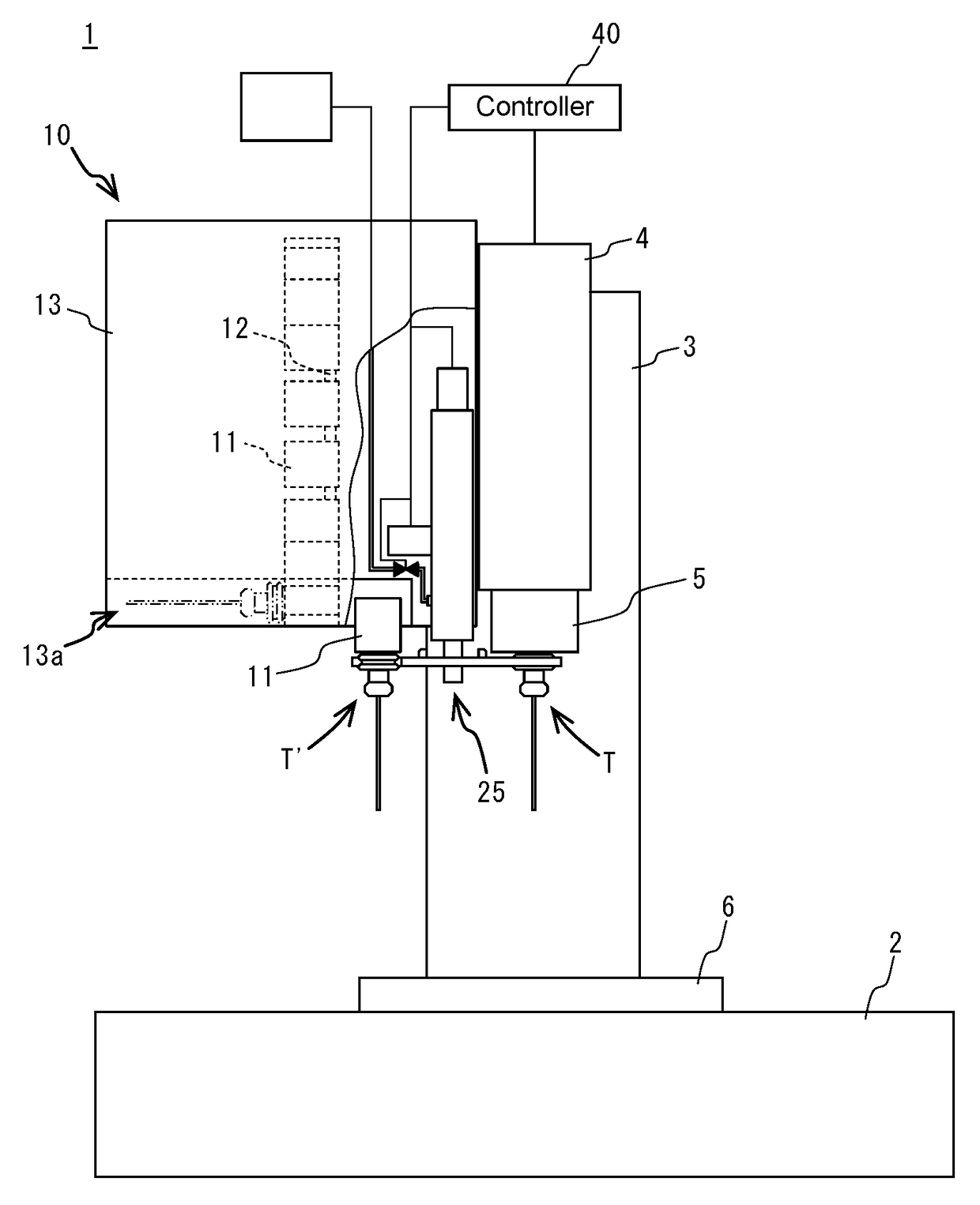
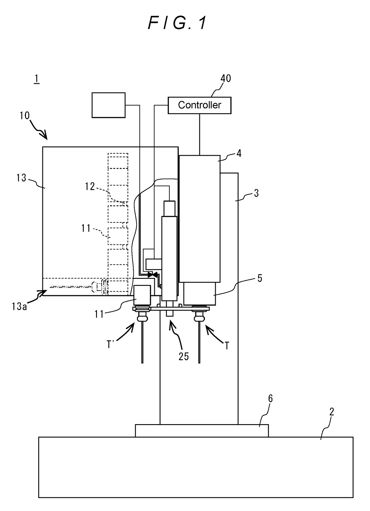
[0052]As shown in FIG. 1, a machine tool 1 in this embodiment is a vertical machining center, and is composed of a bed 2, a column 3 erected on the bed 2, a spindle head 4 supported by the column 3 to be moved in a vertical direction by an appropriate feed mechanism, a spindle 5 supported by the spindle head 4 to be rotatable about an axis thereof and rotated by an appropriate spindle motor incorporated in the spindle head 4, a table 6 disposed on the bed 2 below the spindle 5, a tool magazine 10 disposed at a side of the spindle head 4, a tool changer 20 provided on the tool magazine 10 for changing a tool T attached to the spindle 5 with a tool T′ stored in a tool pot 11 of the tool magazine 10, and a controller 40 controlling operations of the above-mentioned components.

[0053]The tool magazine 10 is composed of a plurality of tool pots 11 holding tools T′, a circular...


PUM


Abstract

A tool changer is composed of a support shaft, a forward/backward movement drive motor moving the support shaft upward and downward, a rotation drive motor rotating the support shaft about an axis, a tool change arm having tool grippers formed at both ends thereof, and an air blow mechanism discharging compressed air to a tool and a next tool gripped by the tool grippers. In tool change using this tool changer, in a positioning operation, the tool change arm is rotated by degrees and compressed air is discharged toward the tool and the next tool by the air blow mechanism.

Description

BACKGROUND[0001]Field of the Disclosure[0002]The present invention relates to a tool changing method that changes a tool attached to a spindle of a machine tool with a next tool positioned at a standby position, and to a tool changer used therefor. More particularly, the present invention relates to a tool changing method and a tool changer which are capable of removing chips and the like adhering to the tools at the time of tool change.[0003]Background of the Disclosure[0004]In the field of machine tools having a tool changer, in changing a tool attached to a spindle, chips may adhere to a tapered portion of the tool, or the tool with chips adhering thereto may be stored into a tool magazine and then the chips may fall off the tool and adhere to tapered portions of other tools. It is known that there is a problem that, if such a tool with chips adhering to its tapered portion is attached to the spindle, the adhering chips cause the tool to be attached with an axis of the tool not a...

Claims


Application Information

Patent Timeline
Patent Type & Authority Applications(United States)
IPC IPC(8): B23Q3/157B23Q11/00
CPCB23Q11/005B23Q3/1574B23Q3/15713B23Q11/0042B23Q2003/155439Y10T483/1767Y10T483/10Y10T483/15Y10T483/1755Y02P70/10B23Q3/15746B23Q3/15503
Inventor KANAMOTO, MASAOSAITO, YUTAKA
Owner DMG MORI CO LTD
Why Eureka
Try Eureka