Casting die

a technology of casting dies and dies, applied in the field of dies, can solve the problems of undesirable variation in the shape of cast or forged components, reduce the life of dies, and reduce material usage, and reduce the effect of thermal and contraction stresses

Active Publication Date: 2018-11-13
ROLLS ROYCE PLC
View PDF8 Cites 0 Cited by
  • Summary
  • Abstract
  • Description
  • Claims
  • Application Information

AI Technical Summary

Benefits of technology

[0009]By providing walls having an equal / uniform width to space the cavities in the rear surface, thermal and contraction stresses are reduced thus allowing the cast component to be manufactured nearer to net-shape such that material usage is reduced and the cast / forged component requires less machining.

Problems solved by technology

The variation in the thickness of the die / walls leads to thermal and contraction stresses which can reduce the life of the die and, over time and cycles lead to distortion of the die which, in turn can lead to undesirable variation in the shape of the cast or forged component.

Method used


Image

  • Casting die
  • Casting die
  • Casting die

Examples


Embodiment Construction

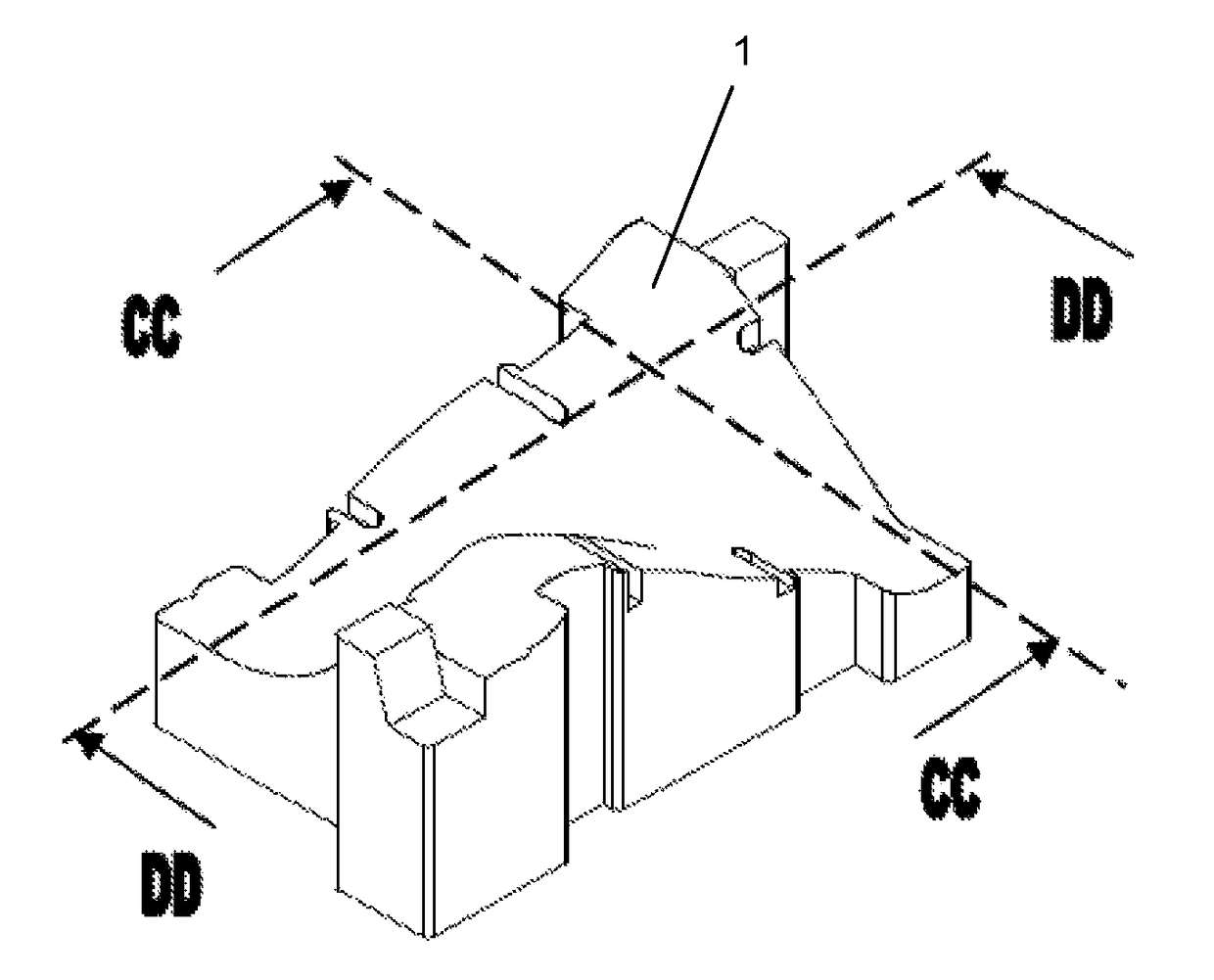
[0036]As shown in FIGS. 2a-d, a first embodiment of the present invention provides a casting die having a forming surface 1 and an opposing rear surface 2.

[0037]In use, the forming surface 1 is used to define one half of a mould cavity and to form superplastic or liquid material e.g. molten metal or metal in its plastic form into the shape desired for cast, forged, or superplastically formed component.

[0038]The rear surface has a width dimension (extending in the direction of line CC) and a longer length dimension (extending in the direction of line DD).

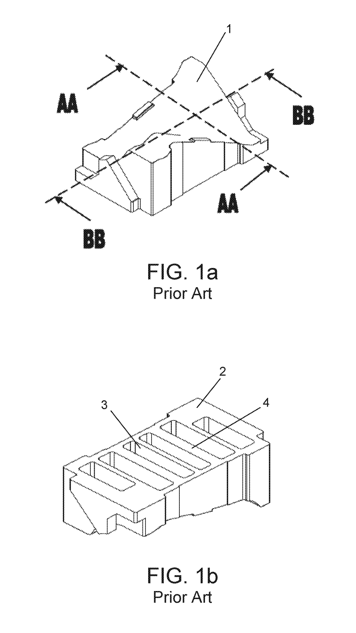
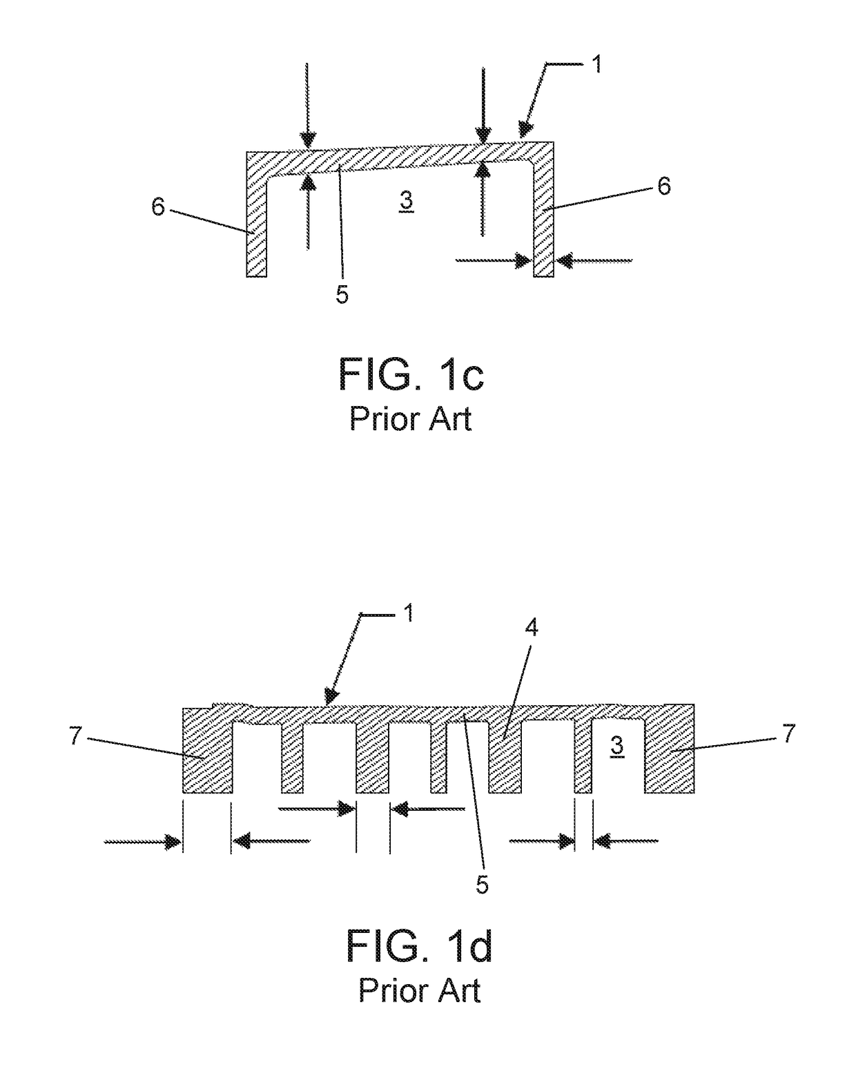
[0039]The rear surface has a plurality of rectangular cavities 3′ defined and mutually spaced by walls 4 having an axial extension coincident with the width dimension of the die and a transverse wall 6 having an axial extension coincident with the length dimension of the die.

[0040]The die further comprises opposing lateral edge walls 7 (having an axial extension coincident with the width of the die) and opposing transverse edge walls...


PUM

PropertyMeasurementUnit
angleaaaaaaaaaa
angleaaaaaaaaaa
widthaaaaaaaaaa

Abstract

The present invention provides a casting / hot forging die having a forming surface and an opposing rear surface. The rear surface has a plurality of cavities spaced by a plurality of walls. Each of the plurality of walls has a substantially equal width. At least one transverse wall may also be provided such that the walls define a grid spacing a series of rectangular or triangular cavities.

Description

FIELD OF THE INVENTION[0001]The present invention relates to a die for use in die casting or hot forging of components e.g. components such as aerofoils for gas turbine engines.BACKGROUND OF THE INVENTION[0002]Components such as aerofoils for gas turbines engines are typically super plastically formed in a die cavity which is defined by two opposing dies. Each die has a forming surface 1 which shapes the material into the desired component form (as shown in FIG. 1a) and an opposing rear surface 2 (as shown in FIG. 1b).[0003]Cavities 3 are typically formed into the rear surface 2 of the die in order to reduce the thermal mass of the die which, in turn, reduces cooling of the furnace upon introduction of the die and reduces heat retention by the die after removal from the furnace.[0004]The cavities 3 in the rear surface 2 of the die are typically separated by a plurality of walls 4 (as shown in FIG. 1d). The walls help increase the strength of the die to allow it to withstand press fo...

Claims


Application Information

Patent Timeline
Patent Type & Authority Patents(United States)
IPC IPC(8): B22C9/06B21K5/20B21K3/04B22D17/22
CPCB22C9/06B22D17/22B21K5/20B21K3/04
Inventor VEEVERS, CHRISTOPHER R
Owner ROLLS ROYCE PLC
Why Eureka
Try Eureka