Damper for vehicles

a technology for dampers and vehicles, applied in the direction of shock absorbers, machine supports, transportation and packaging, etc., can solve the problems of increased mass dampers, increased weight of mass dampers, and ineffective with plural resonances, etc., and achieve the effect of lightening the weigh

Inactive Publication Date: 2002-08-27
SUMITOMO RIKO CO LTD
View PDF13 Cites 57 Cited by
  • Summary
  • Abstract
  • Description
  • Claims
  • Application Information

AI Technical Summary

Benefits of technology

The present invention is made in view of the above circumstances and has a subject matter or purpose to provide a vibration restraining apparatus for vehicle which can be lightened in weight, does not have the temperature dependency, and can perform the vibration restraining effect for plural resonances having different frequencies.

Problems solved by technology

If a natural resonance occurs in these vibration transmitting members, the vibration transmission to the vehicle body is amplified to cause noise in the vehicle room and vibration of vehicle frame.
However, more mass needs to be added for obtaining sufficient vibration restraining effect by the mass damper, which increases the weight of the mass damper.
However, the resonance frequency of this dynamic damper is determined based on weight of the mass body and spring constant of the rubber elastic body, so the dynamic damper can restrain the vibration at only one frequency area in the resonance occurred in the vibration transmitting member, but is not effective with respect to plural resonances.
Accordingly, restraining the vibrations in many directions simultaneously by one dynamic damper is difficult.
Also, the spring constant of the rubber elastic body used as the spring easily varies depending on temperature and has a large temperature dependency, so that the vibration restraining effect is deteriorated at a high temperature and at a low temperature.
However, such vibration restraining member needs to be adhered to the vibration transmitting member in rather broad area, and has larger weight due to a forming material of relatively large specific gravity.
Thus, the mass damper, dynamic damper and vibration restraining member which have been conventionally used have above problems.

Method used


Image

  • Damper for vehicles
  • Damper for vehicles
  • Damper for vehicles

Examples


embodiment 1

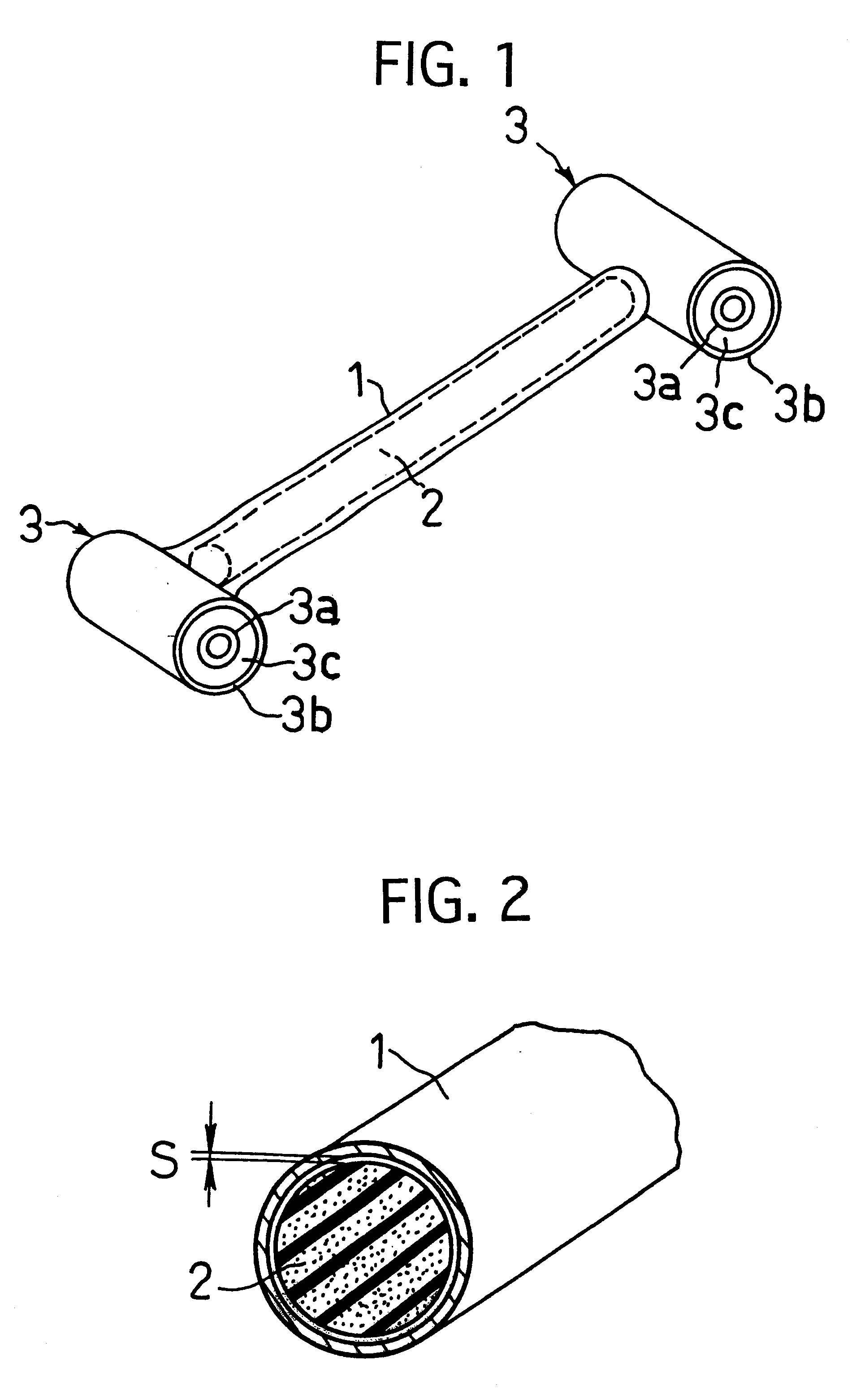
FIG. 1 is a perspective view showing a vibration restraining apparatus for vehicle of this embodiment, and FIG. 2 is a broken perspective view of the same.

The vibration restraining apparatus for vehicle of this embodiment is constructed by using a suspension arm for an automobile of hollow pipe shape having an inner space as a housing. This suspension arm is, as shown in FIGS. 1 and 2, constructed by a tubular arm body 1, a filled member 2 filled and disposed in an inner space of the arm body 1 in a non-adhered state with leaving a gap, and a pair of connecting members 3, 3 respectively fixed to both ends of the arm body 1, as the main parts.

The arm body 1 is made of an aluminium alloy, and formed into a tubular shape extending lineally in substantially constant diameter.

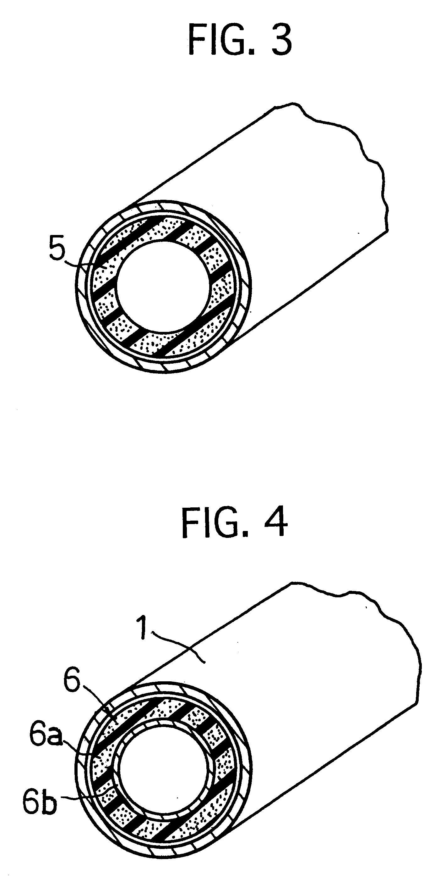
The whole filled member 2 is constructed by an elastic foamed body formed by foaming a filled member forming material by the foaming magnification of three times. The filled member forming material is produced by mi...

embodiment 2

FIG. 14 is a cross-sections view showing a vibration restraining apparatus for vehicle of an embodiment 2, and FIG. 15 is a broken perspective view of the same.

The vibration restraining apparatus for the vehicle of this embodiment is set on a subframe of an automobile. This vibration restraining apparatus for the vehicle is, as shown in FIGS. 14 and 15, constructed by a housing 8 having an inner cavity, and a filled member 9 is sealed into the inner space of the housing 8 in a non-adhered state with leaving a gap S.

The housing 8 is comprised of a body portion 8a and is formed into a tubular shape having substantially constant diameter by an aluminium alloy, pair of plug portions 8b, 8b made of an aluminium alloy and attached to both ends of the body portion 8a respectively by welding to seal openings. A closed inner space is formed inside the housing 8 by sealing the both end openings of the body portion 8a by the paired plug portions 8b, 8b. This housing 8 has an elasticity rate mo...

embodiment 3

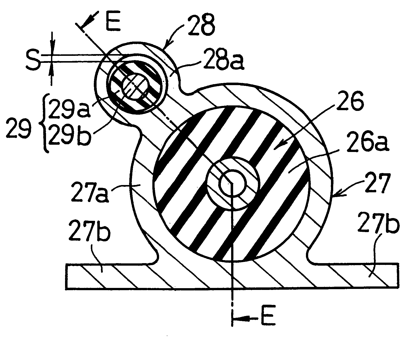
FIG. 20 is a partially broken plan view showing a vibration restraining apparatus for vehicle of this embodiment, and FIG. 21 is a cross-sectional view of the same taken along line A--A in FIG. 20.

The vibration restraining apparatus for vehicle of this embodiment is attached to a sub frame of an automobile, and has the same basic construction as that in the above embodiment 2, except for the provision of a bracket 15. That is, this vibration restraining apparatus for vehicle is, as shown in FIGS. 20 and 21, comprised of a housing 13 having an inner space, a filled member 14 filled in the inner space of the housing 13 in a non-adhered state with leaving a gap S, and a bracket 15 attached to the housing 13.

The housing 13 is comprised of a body portion 13a formed into a tubular shape having substantially constant diameter by an aluminium alloy, a pair of plug portions 13b, 13b made of an aluminium alloy and attached to both ends of the body portion 8a respectively by welding to seal op...


PUM


Abstract

A vibration restraining apparatus for vehicle of the present invention is comprised of a housing formed by a rigid material and having an inner space, and fixed to a vibration transmitting member; a filled member sealed in the inner space of said housing in a non-adhered state with leaving a gap with respect to a vibrating direction of said housing, and formed by an elastic body at least at a surface thereof. When the housing resonates by vibration transmitted from the vibration transmitting member, the filled member contacts inner surface parts located at both sides of the housing in a vibrating direction thereof to exercise a damping character due to an energy loss caused by a sliding friction and a collision. Thus, a large damping character occurs inside of the housing to reduce vibration of the housing effectively. As a result, vibration of the vibration transmitting member is effectively reduced. The vibration restraining apparatus for vehicle of the present invention can be lightened in weight, does not have a temperature dependency, and can exercise the vibration restraining effect for plural resonances having different frequencies.

Description

This invention relates to a vibration restraining apparatus for a vehicle attached to a vibration transmitting member to restrain a harmful vibration occurring therein. Here, the vibration transmitting member includes a suspension arm, sub frame, body panel, engine mounting bracket, engine unit or exhausting device of an automobile, and an arm member or a body panel of an electric train.A running vehicle such as an automobile for example generates a vibration by operation of an engine as a power source, and the generated vibration is inputted into the road through surface during running of the vehicle. These vibrations are in turn transmitted to the vehicle body through an engine mounting bracket or a vehicle body frame supporting an engine unit or a suspension arm or sub frame connected to wheels. If a natural resonance occurs in these vibration transmitting members, the vibration transmission to the vehicle body is amplified to cause noise in the vehicle room and vibration of vehi...

Claims


Application Information

Patent Timeline
Patent Type & Authority Patents(United States)
IPC IPC(8): B60G13/00B60G13/16F16F15/02F16F7/08F16F7/10F16F7/00
CPCB60G13/16F16F7/08F16F7/10F16F15/02B60G2202/25B60G2206/11
Inventor KATO, RENTAROYASUMOTO, YOSHINORIHAMADA, MASAAKIIKAGA, SYUJIMAENO, HAJIMEHATTORI, SHIGEMITSU
Owner SUMITOMO RIKO CO LTD
Why Eureka
Try Eureka