

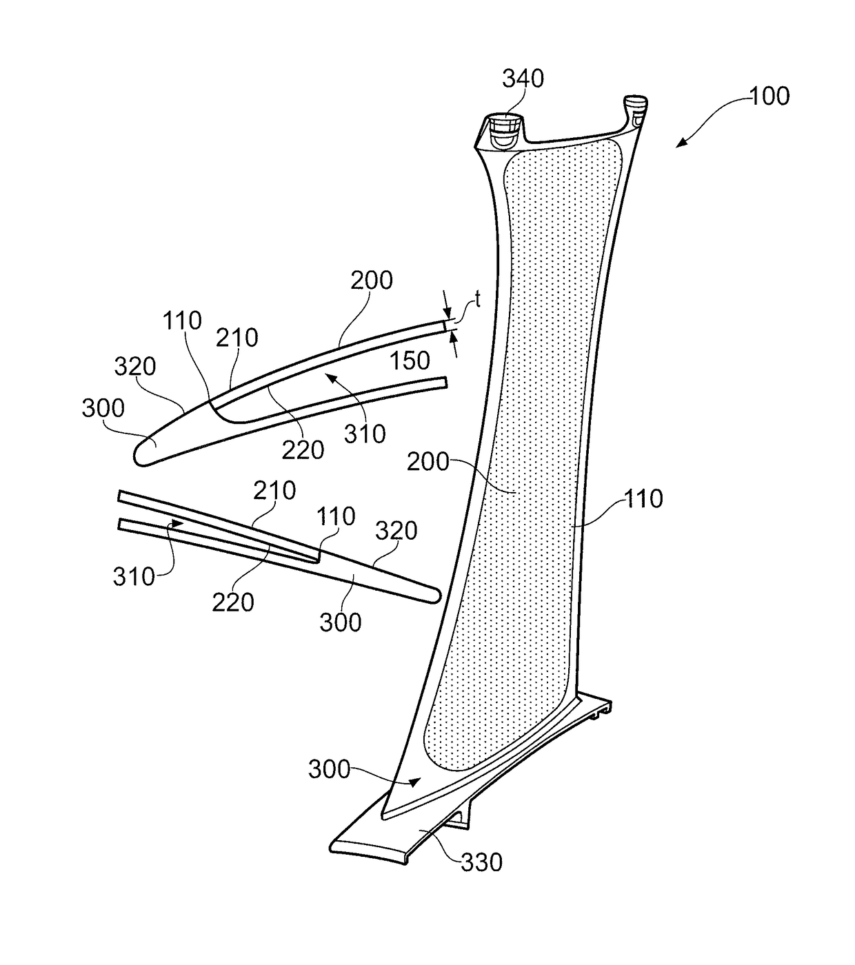
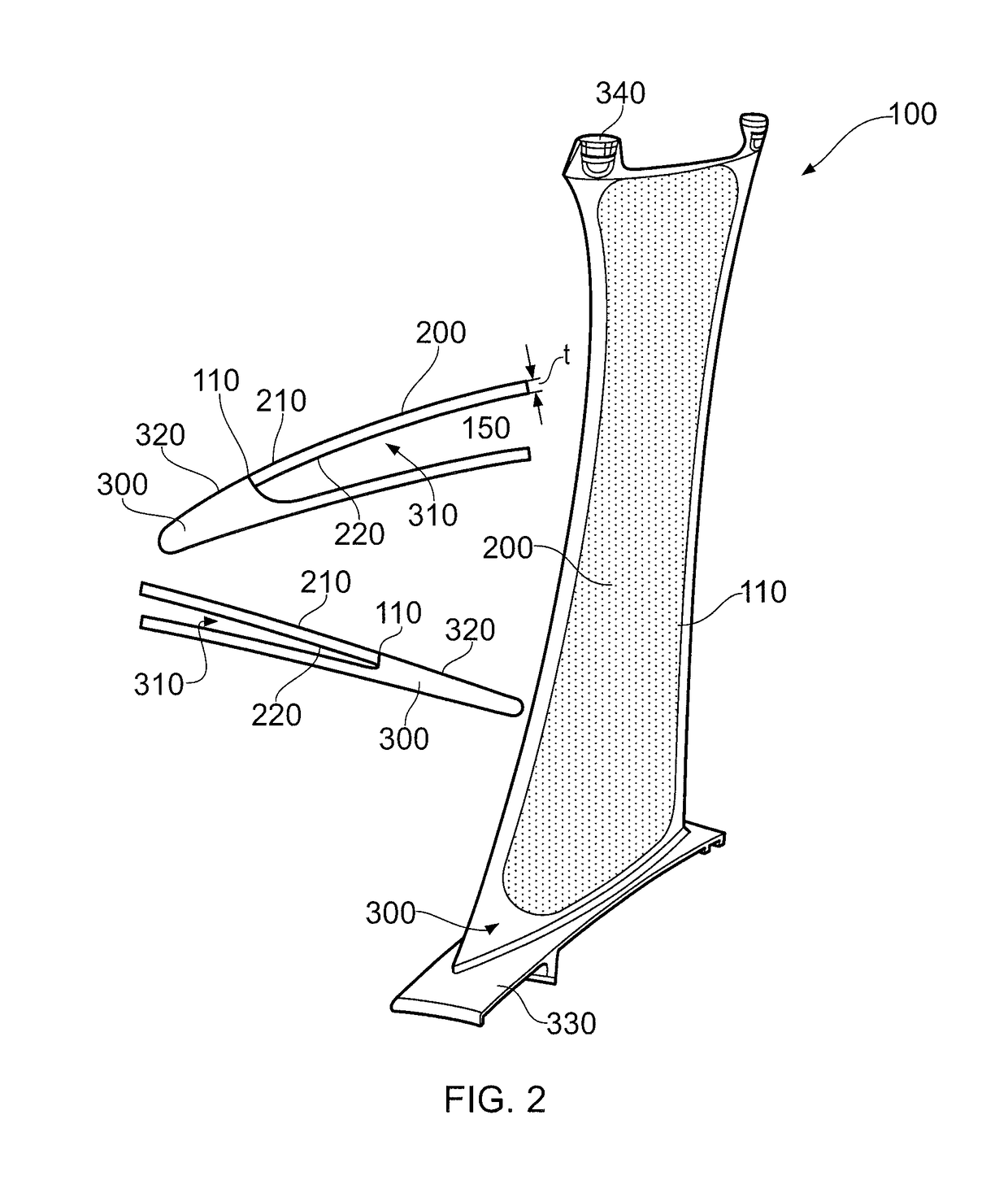
Manufacture of hollow aerofoil
a technology of aerofoil and shell, which is applied in the direction of machines/engines, climate sustainability, sustainable transportation, etc., can solve the problems of insufficient dimensional tolerance, high processing cost, and inability to accurately predict the dimensional tolerance, so as to reduce the amount of material ejected or spattered from the weld area during welding, and/or substantially eliminate the effect of spatter
- Summary
- Abstract
- Description
- Claims
- Application Information
AI Technical Summary
Benefits of technology
Problems solved by technology
Method used
Image

Examples
Embodiment Construction
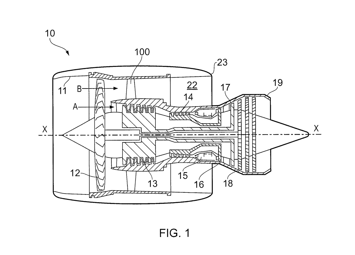
[0059]With reference to FIG. 1, a ducted fan gas turbine engine generally indicated at 10 has a principal and rotational axis X-X. The direction X-X may be referred to as the axial direction of the engine. The engine 10 comprises, in axial flow series, an air intake 11, a propulsive fan 12, an intermediate pressure compressor 13, a high-pressure compressor 14, combustion equipment 15, a high-pressure turbine 16, an intermediate pressure turbine 17, a low-pressure turbine 18 and a core engine exhaust nozzle 19. A nacelle generally surrounds the engine 10 and defines the intake 11, a bypass duct 22 and a bypass exhaust nozzle 23.
[0060]The gas turbine engine 10 works in a conventional manner so that air entering the intake 11 is accelerated by the fan 12 to produce two air flows: a first air flow A into the intermediate pressure compressor 13 and a second air flow B (which may be referred to as a bypass flow B) which passes through the bypass duct 22 to provide propulsive thrust. The i...
PUM
| Property | Measurement | Unit |
|---|---|---|
| angle | aaaaa | aaaaa |
| perimeter | aaaaa | aaaaa |
| suction | aaaaa | aaaaa |
Abstract
Description
Claims
Application Information