
Door lock

a door lock and door lock technology, applied in the field of door locks, can solve the problems of difficult implementation of electrically activated home door locks, unfavorable users, and inability to perform general functions,

Inactive Publication Date: 2017-07-06
GOOGLE LLC
View PDF1 Cites 23 Cited by
  • Summary
  • Abstract
  • Description
  • Claims
  • Application Information

AI Technical Summary

Benefits of technology

The disclosed patent describes a door lock apparatus that uses a male component and a strike to lock a door. The male component has multiple parallel subcomponents that are positioned in a strike and a bed of sensors in a box. When the male component is moved into the strike, the sensors detect the subcomponents and an alarm is triggered if there is not a sufficient number of subcomponents in contact with the sensors. The lock actuator and male component can be positioned in the door or the door jamb, and the power source can be a battery or a household power source. The parallel subcomponents are approximately 2 millimeters in width and can be hexagonal in cross-section. The apparatus can also include an authentication module for opening the door, a door handle, a proximity sensor, and a handle actuator. The method involves determining the number of parallel subcomponents and comparing it to a threshold minimum to determine if the door is securely locked.

Problems solved by technology

Such actions are not generally difficult for a user to perform.
An electrically activated home door lock may be difficult to implement, however.
The physical configuration of a door may not be stable over time, for example, which could hamper the operation of an electromechanical lock.
A door or jamb may sag or warp over time, so that eventually a deadbolt may no longer fit easily through a strike.
Moreover, a door in a home may not have a ready power source with which to power a lock apparatus.

Method used


Image

  • Door lock
  • Door lock
  • Door lock

Examples


Embodiment Construction

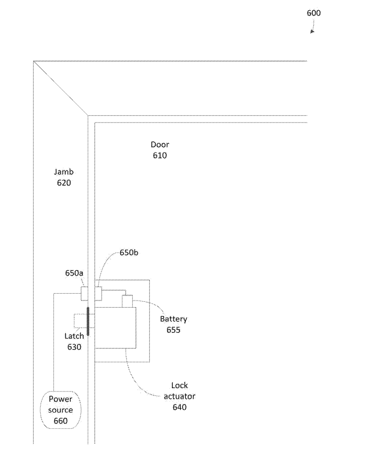
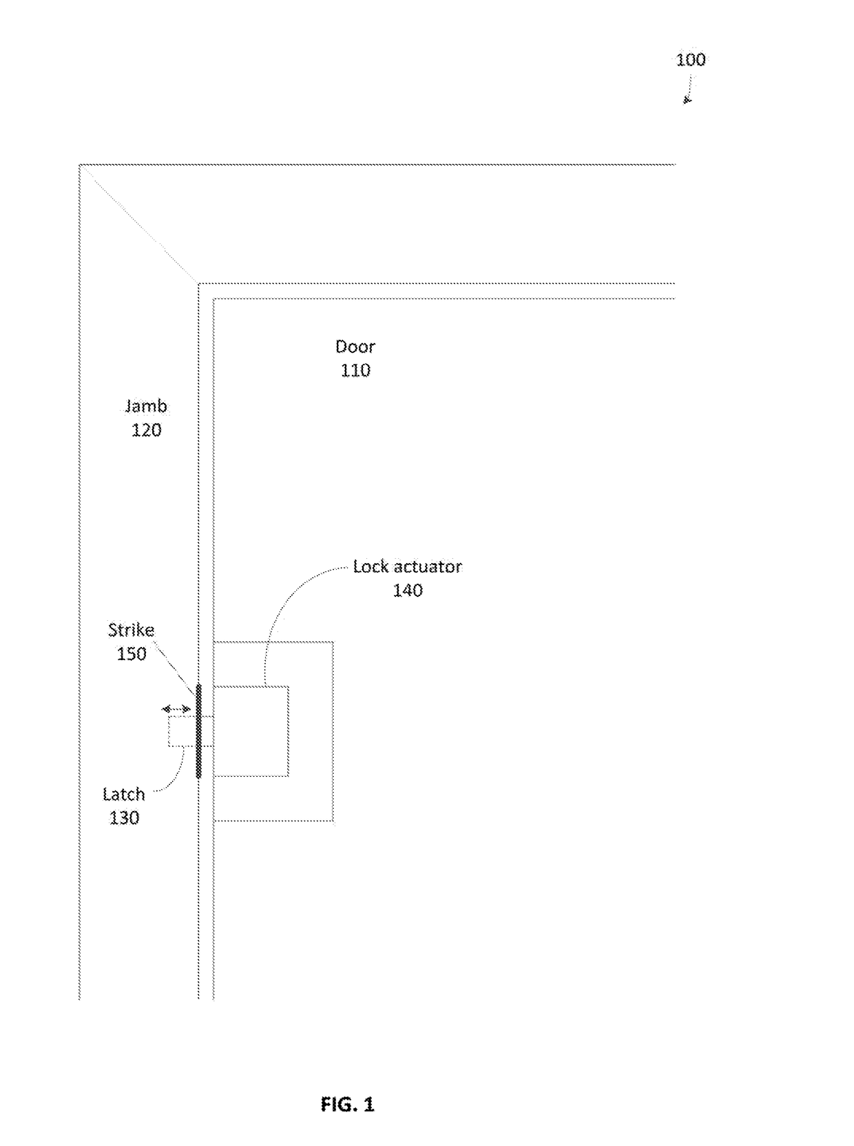
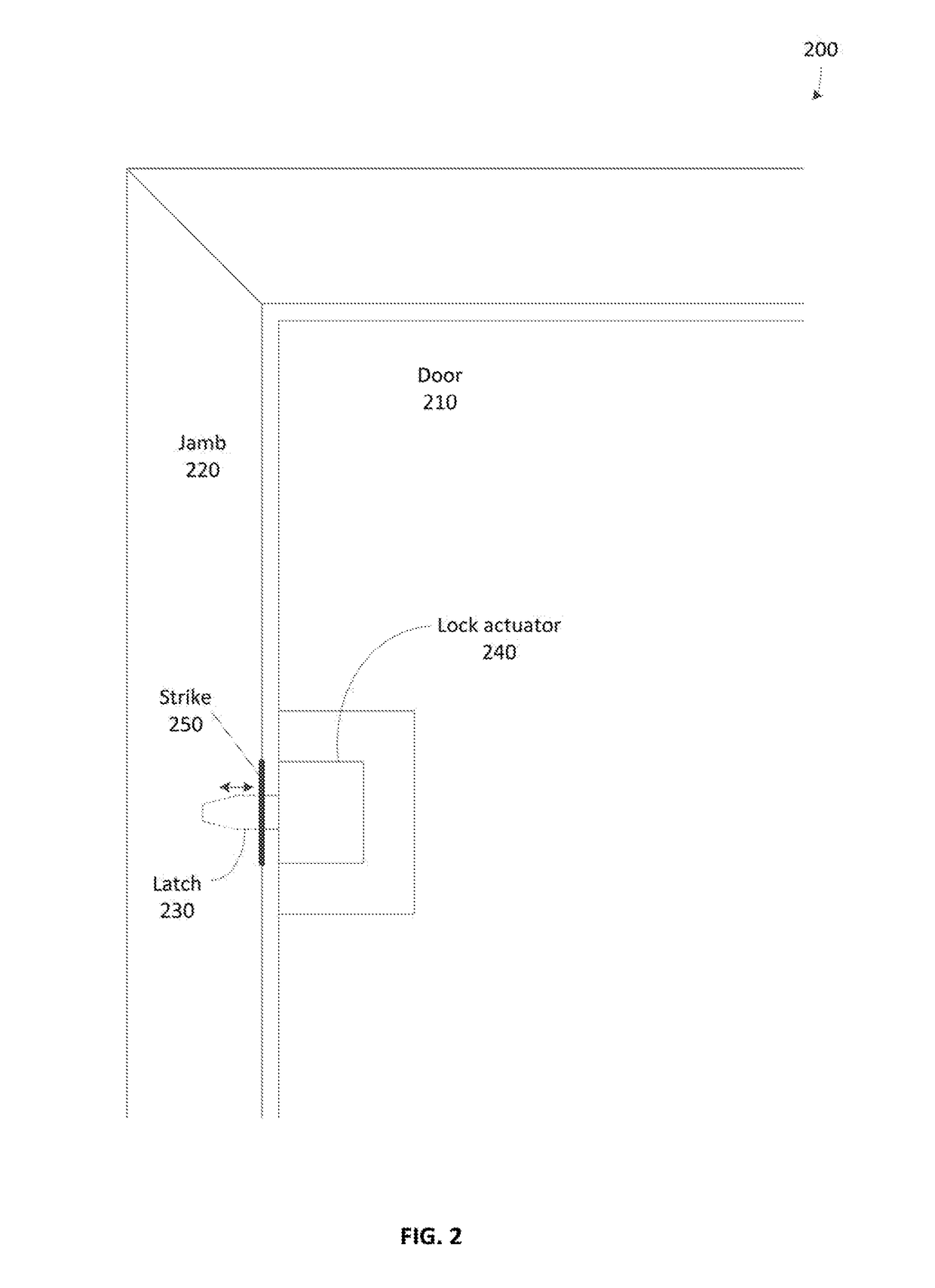
[0033]According to an embodiment of the disclosed subject matter, a door lock apparatus is described herein, comprising a male component; a connection to a power source; a lock actuator, powered by the power source and configured to move the male component at least partially through a strike and into a box beyond the strike in the path of the male component to lock a door, wherein the male component comprises a plurality of parallel subcomponents oriented lengthwise in the direction of a path of the male component; a bed of sensors positioned in the box and configured to sense a number of parallel subcomponents that contact the bed after the male component has been moved into the box; and an alarm in communication with the bed, wherein an alert or alarm condition is triggered when an attempt is made to lock the door and an insufficient number of parallel subcomponents contacting the bed has been sensed by the bed of sensors.

[0034]In an embodiment, a door may be locked by the movemen...


PUM


Abstract

A door lock apparatus, comprising a male component; a connection to a power source; a lock actuator, powered by the power source and configured to move the male component at least partially through a strike and into a box beyond the strike in the path of the male component to lock a door, wherein the male component comprises a plurality of parallel subcomponents oriented lengthwise in the direction of a path of the male component; a bed of sensors positioned in the box and configured to sense a number of parallel subcomponents that contact the bed after the male component has been moved into the box; and an alarm in communication with the bed, wherein the alarm is triggered when an attempt is made to lock the door and an insufficient number of parallel subcomponents contacting the bed has been sensed by the bed of sensors.

Description

BACKGROUND[0001]Traditional home door locks require a user to manually set a deadbolt and / or a latch mechanism to lock the door. This may be accomplished by turning a knob or pressing a mechanical button, for example. Such actions are not generally difficult for a user to perform. Nonetheless, there can be advantages to a door lock apparatus where the lock is electrically activated. For example, such a lock could be electrically connected to one or more sensors located elsewhere. If an attempted intrusion is detected at the home, an alarm condition may be raised. As a part of this alarm condition, electrically powered door locks may be automatically set to secure the home. If a fire is detected by a sensor, a different alarm condition may be asserted, whereby electrically powered door locks may be automatically reset, i.e., unlocked. This allows occupants to easily exit the home, particularly those who may have difficulty manipulating a traditional lock, such as children or elderly ...

Claims


Application Information

Patent Timeline
Patent Type & Authority Applications(United States)
IPC IPC(8): E05B45/00E05F15/72H02J7/02E06B5/11G07C9/00E05B47/00E05B41/00
CPCE05B45/00E05B47/0001E05F15/72E05B41/00E06B5/11E05B47/0046E05B2047/0097H02J7/025E05B2047/0048E05B2047/0071E05B2047/0067E05B2047/0094G07C9/00563E05B45/06E05B47/0012E05B47/026E05B63/242E05B2047/0059E05B2047/0061E05B2047/0062E05B2047/0064G07C2009/00634
Inventor MITTLEMAN, ADAM DUCKWORTHPRIVITERA, PETERFILSON, JOHN BENJAMINBOOTH, KEVINJENKS, KENNETH ARTHURKRAZ, MARKCHAMBERLAIN, JASON
Owner GOOGLE LLC
Learn More