
Ink-Jet Recording Apparatus

a recording apparatus and a technology of a nozzle are applied in the field of a recording apparatus, which can solve the problems of affecting the image quality of an image recorded on the sheet, the loss of the waveform shape of the sheet, and the change of the spacing between the sheet and the nozzle, so as to achieve the effect of favorable maintenance of the waveform shape of the sheet and the reduction of the loss of the waveform shape when the sheet enters the roller

Active Publication Date: 2017-08-03
BROTHER KOGYO KK
View PDF0 Cites 0 Cited by
  • Summary
  • Abstract
  • Description
  • Claims
  • Application Information

AI Technical Summary

Benefits of technology

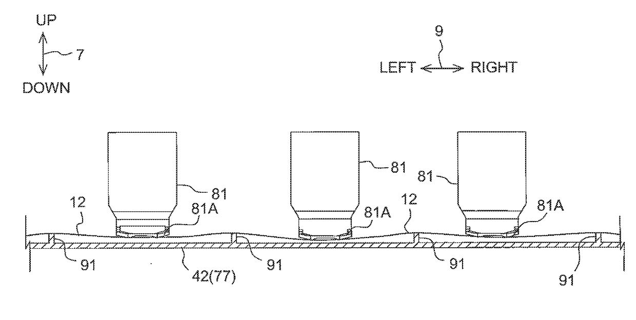
The ink-jet recording apparatus in this patent has a design that helps keep the sheet of paper on the table in a specific shape, called a waveform shape. This is important because the ink gets printed on the paper when it is in this specific shape, and if it changes too much during the printing process, the ink may not print correctly. By maintaining the waveform shape, the ink-jet recording apparatus can produce higher-quality prints.

Problems solved by technology

When floating-up of the sheet occurs at a position facing a nozzle, a spacing between the sheet and the nozzle ends up changing, and there is a risk that an effect ends up being exerted on image quality of an image recorded on the sheet.
However, according to findings of the inventors, in the above-mentioned ink-jet recording apparatus, the following problem occurs.
As a result, there is a risk that the waveform shape of not only the portion that has entered the roller in the sheet, but also a portion supported by the ribs in the sheet, is lost.
If the waveform shape of the portion supported by the ribs in the sheet is lost, there is a risk of an effect being exerted on the image recorded on the sheet.

Method used


Image

  • Ink-Jet Recording Apparatus
  • Ink-Jet Recording Apparatus
  • Ink-Jet Recording Apparatus

Examples


Embodiment Construction

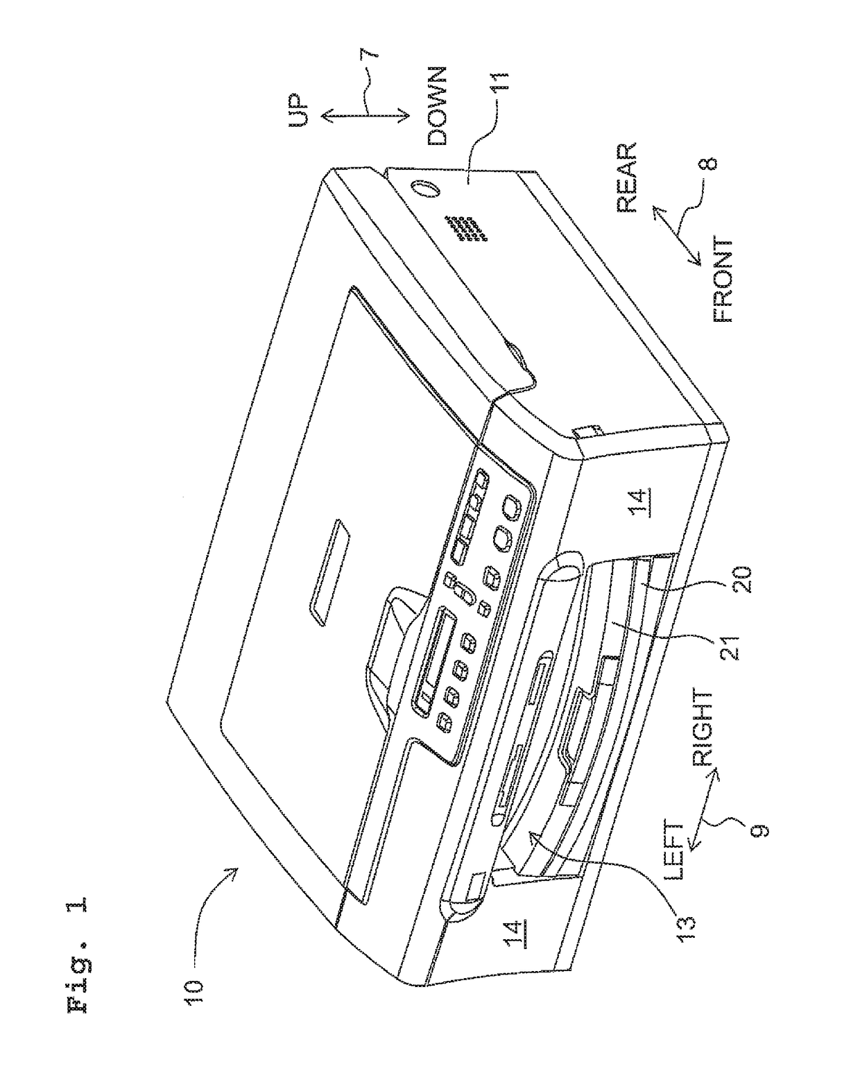
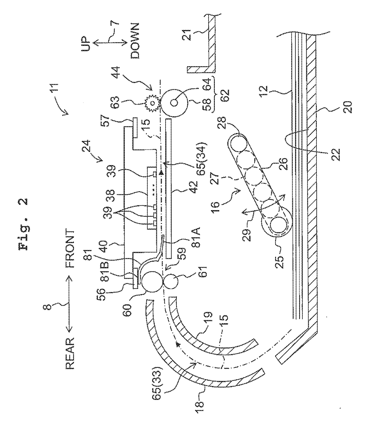
[0025]An embodiment of the present teaching will be described below. Note that the embodiment described below is merely an example of the present teaching, and it goes without saying that the embodiment of the present teaching may be appropriately changed in a range that does not alter the gist of the present teaching. Moreover, in the description below, an up-down direction 7 is defined with reference to a state in which a multifunction peripheral 10 is usably disposed (state of FIG. 1), a front-rear direction 8 is defined assuming a surface provided with an opening 13 to be a front surface 14, and a left-right direction 9 is defined viewing the multifunction peripheral 10 from the front. The up-down direction 7, the front-rear direction 8, and the left-right direction 9 are orthogonal to each other.

[Overall Structure of Multifunction Peripheral 10]

[0026]As depicted in FIG. 1, the multifunction peripheral 10 (an example of an ink-jet recording apparatus) is roughly formed into a th...


PUM


Abstract

An ink-jet recording apparatus is provided. The ink-jet recording apparatus includes: a plurality of rollers that convey a sheet in a conveyance direction; a platen; a recording unit; a plurality of first ribs provided in the platen; and a plurality of second ribs provided between the first ribs and the rollers in the conveyance direction. The plurality of rollers, the plurality of first ribs, and the plurality of second ribs are each disposed in a position where at least parts of them overlap in the width direction, and a length in the width direction of each of the supporting surfaces of the plurality of second ribs is longer than that in the width direction of each of the supporting surfaces of the plurality of first ribs, and is shorter than that in the width direction of an abutting surface on the sheet in each of the plurality of rollers.

Description

CROSS REFERENCE TO RELATED APPLICATION[0001]The present application claims priority from Japanese Patent Application No. 2016-016670 filed on Jan. 29, 2016, the disclosure of which is incorporated herein by reference in its entirety.FIELD OF THE INVENTION[0002]The present invention relates to an ink-jet recording apparatus that records an image on a sheet by discharging ink droplets from nozzles.DESCRIPTION OF THE RELATED ART[0003]In an ink-jet recording apparatus, a sheet being conveyed along a conveyance path formed inside the apparatus sometimes ends up floating up from a platen supporting said sheet. When floating-up of the sheet occurs at a position facing a nozzle, a spacing between the sheet and the nozzle ends up changing, and there is a risk that an effect ends up being exerted on image quality of an image recorded on the sheet.[0004]In order to solve such a problem, conventionally, an ink-jet recording apparatus in which high ribs and low ribs that extend along a conveyanc...

Claims


Application Information

Patent Timeline
Patent Type & Authority Applications(United States)
IPC IPC(8): B41J11/04B41J2/01
CPCB41J2/01B41J11/04B41J11/00B41J11/0045B41J11/06
Inventor SANO, IWANEITO, TSUYOSHIKANAZAWA, GAKURO
Owner BROTHER KOGYO KK
Learn More