Blade of a turbomachine having blade root thermal insulation

Inactive Publication Date: 2017-08-03
MTU AERO ENGINES GMBH
View PDF1 Cites 6 Cited by
  • Summary
  • Abstract
  • Description
  • Claims
  • Application Information

AI Technical Summary

Benefits of technology

[0033]Accordingly, it is possible to operate the blade root of a rotor blade and a blade root receptacle in a rotor disk at different temperatures, such as to also facilitate the use of different materials for blades or blade root regions and structural parts containing the blade receptacle, such as rotor disks. This is advantageous particularly in the case of the new generations of turbomachines or aero engines equipped with a geared turbofan. The demands made in particular on rotor blades in such turbomachines are particularl

Problems solved by technology

Accordingly, both rotor blades and guide blades in the flow duct of the turbomachine have to satisfy high demands, since they can be exposed to high temperatures, high levels of mechanical loading and also aggressive media.
The use of different materials for the blades and adjacent components, such as rotor disks, casing, etc., arises on account of the specific and complex demands for the blades and the associated high costs for the corresponding material for the blades and/or on account of a different demand profile of the components of the turbomachine which are adjacent to the blades, such that the same material as for the blades cannot or should not be used for suc

Method used


Image

  • Blade of a turbomachine having blade root thermal insulation
  • Blade of a turbomachine having blade root thermal insulation
  • Blade of a turbomachine having blade root thermal insulation

Examples


Embodiment Construction

[0039]The particulars shown herein are by way of example and for purposes of illustrative discussion of the embodiments of the present invention only and are presented in the cause of providing what is believed to be the most useful and readily understood description of the principles and conceptual aspects of the present invention. In this regard, no attempt is made to show details of the present invention in more detail than is necessary for the fundamental understanding of the present invention, the description in combination with the drawings making apparent to those of skill in the art how the several forms of the present invention may be embodied in practice.

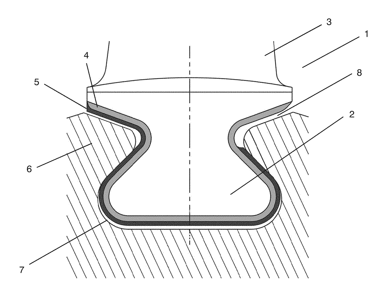
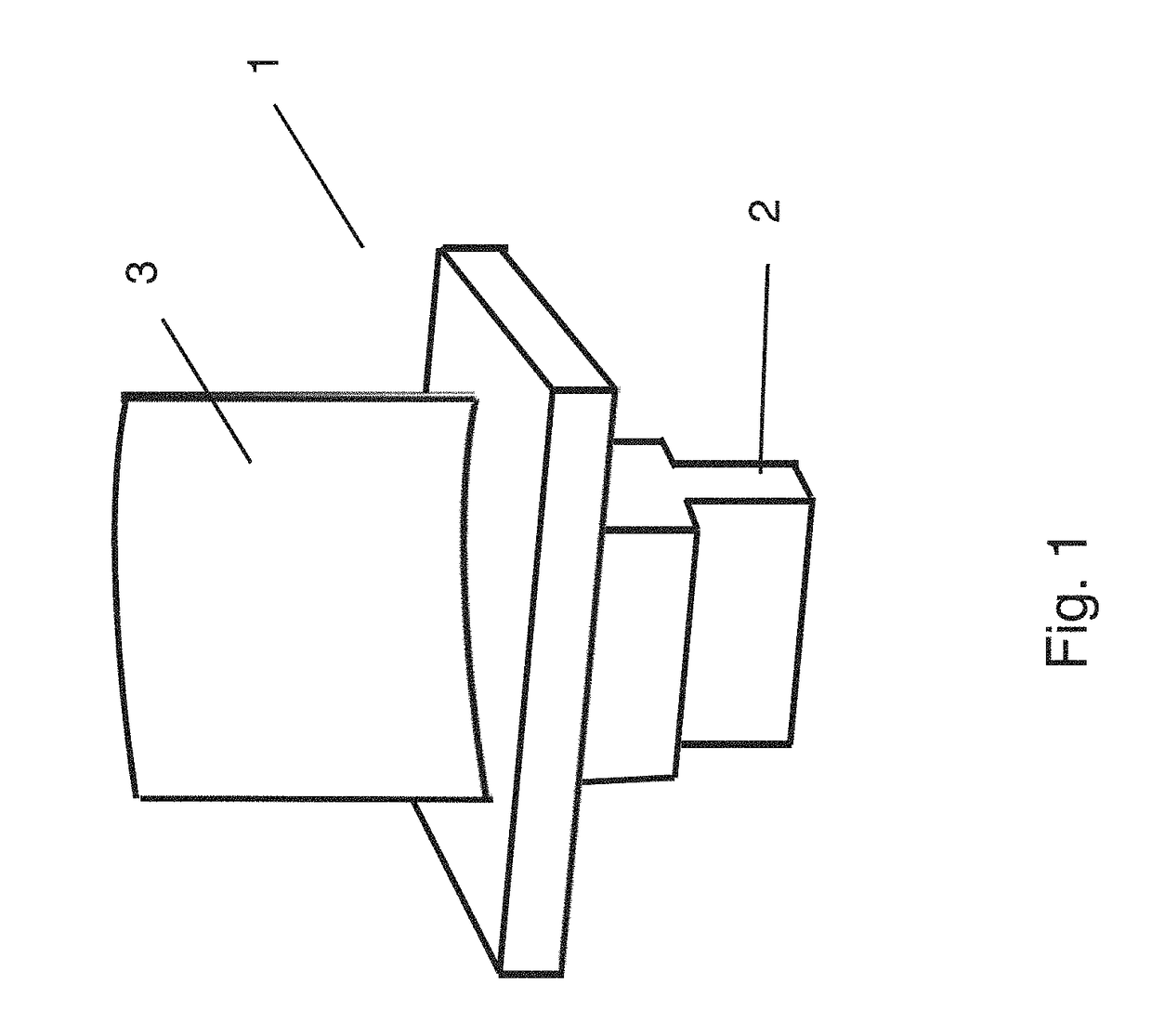
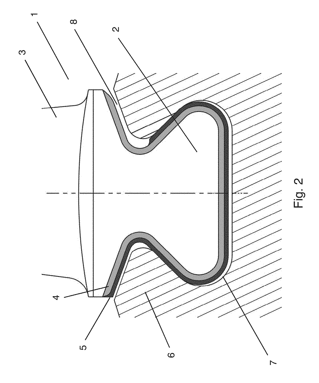
[0040]FIG. 1 shows a schematic example of a blade 1 of a turbomachine, such as for example a gas turbine or an aero engine. The blade 1 shown in FIG. 1 can be arranged, for example, as a rotor blade on a rotor of a turbomachine, wherein the root 2 of the blade 1 is received in a corresponding blade root receptacle (not sho...


PUM

PropertyMeasurementUnit
Temperatureaaaaaaaaaa
Elongation at breakaaaaaaaaaa

Abstract

Disclosed is an arrangement for fastening a blade root of a blade of a turbomachine in a blade root receptacle, with a blade having a blade root of a first material and with a blade root receptacle of a second material, wherein a thermal barrier layer is arranged between the blade root and the blade root receptacle. Further disclosed is a blade having a blade root with a thermal barrier layer and also a method for operating a turbomachine, in which a blade having a blade root is received in a blade root receptacle and a blade root temperature which is above the blade root receptacle temperature is set.

Description

CROSS-REFERENCE TO RELATED APPLICATIONS[0001]The present application claims priority under 35 U.S.C. §119 of German Patent Application No. 102016201523.0, filed Feb. 2, 2016, the entire disclosure of which is expressly incorporated by reference herein.BACKGROUND OF THE INVENTION[0002]1. Field of the Invention[0003]The present invention relates to an arrangement for fastening a blade root of a blade of a turbomachine in a blade root receptacle and also to a blade for a turbomachine and to a method for operating a turbomachine.[0004]2. Discussion of Background Information[0005]Turbomachines, such as stationary gas turbines or aero engines, are provided with a multiplicity of blades, which are fastened as rotor blades on a rotating rotor or are arranged as guide blades (also referred to as guide vanes) in a stationary manner in the turbomachine. In the region of the airfoils of the guide blades and of the rotor blades, the fluid of the turbomachine, such as for example air, is conducte...

Claims


Application Information

Patent Timeline
IPC IPC(8): F01D5/08F01D5/30
CPCF01D5/08F01D5/3007F05D2260/231F05D2220/32F01D5/3092F01D5/284F05D2300/611Y02T50/60
Inventor BOECK, ALEXANDER
Owner MTU AERO ENGINES GMBH
Why Eureka
Try Eureka