Optical image capturing system

Active Publication Date: 2017-08-10
ABILITY OPTO ELECTRONICS TECH
View PDF0 Cites 14 Cited by
  • Summary
  • Abstract
  • Description
  • Claims
  • Application Information

AI Technical Summary

Benefits of technology

[0040]The height of optical system (HOS) may be reduced to achieve the minimization of the optical image capturing system when the absolute value of f1 is larger than f6 (|f1|>f6).
[0041]When |f2|+|f3|+|f4|+|f5| and |f1|+|f6| are satisfied with above relations, at least one of the second through fifth lens elements may have weak positive refractive power or weak negative refractive power. The weak refractive power indicates that an absolute value of the focal length of a specific lens element is greater than 10. When at least one of the second through fifth lens elements has the weak positive refractive power, the positive refractive power of the first lens element can be shared, such that the unnecessary aberration will not appear too ea

Problems solved by technology

The optical image capturing system in prior arts cannot meet the requirement of the higher order camera lens module.
Therefore, how to effectively inc

Method used


Image

  • Optical image capturing system
  • Optical image capturing system
  • Optical image capturing system

Examples


first embodiment (embodiment 1)

The First Embodiment (Embodiment 1)

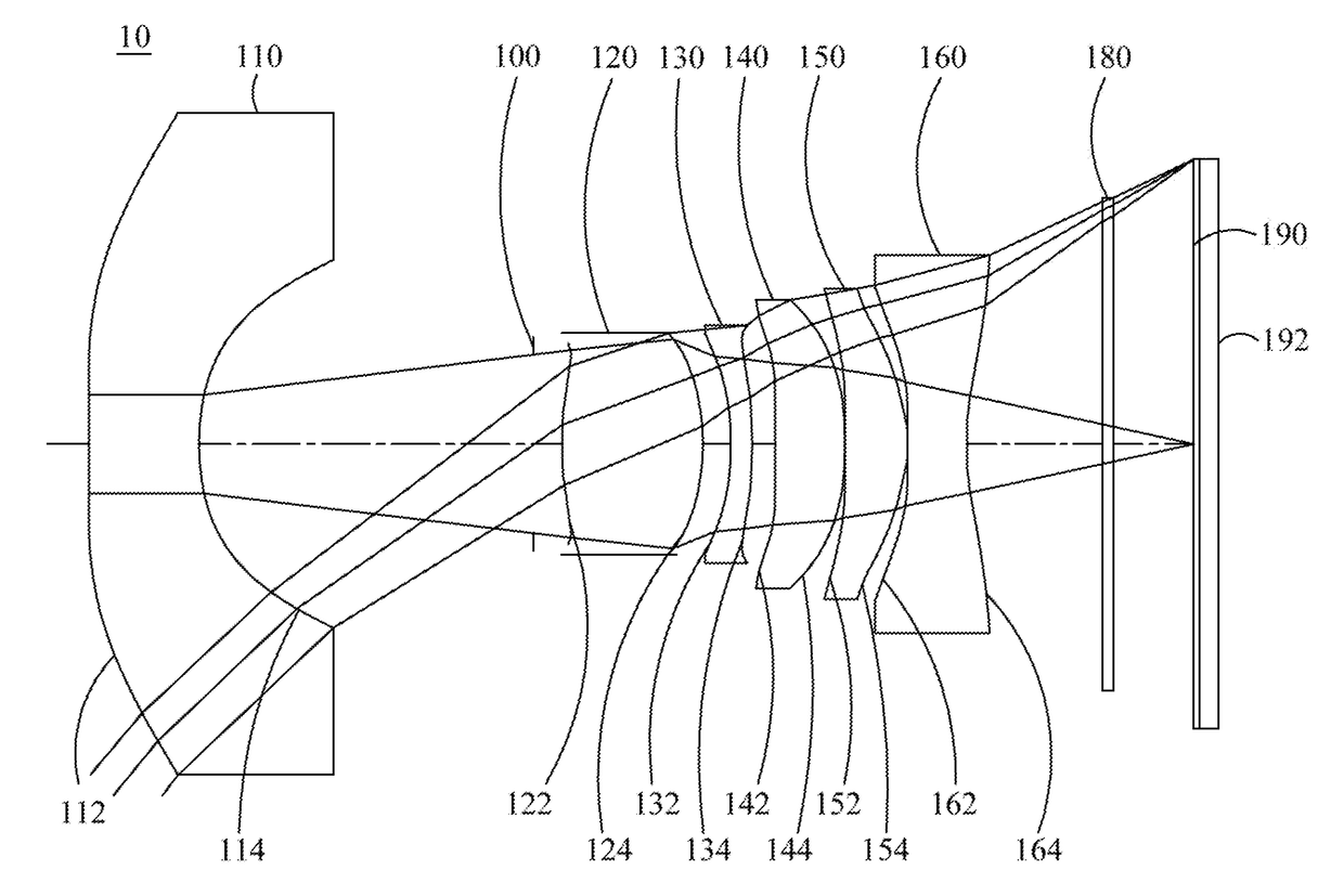
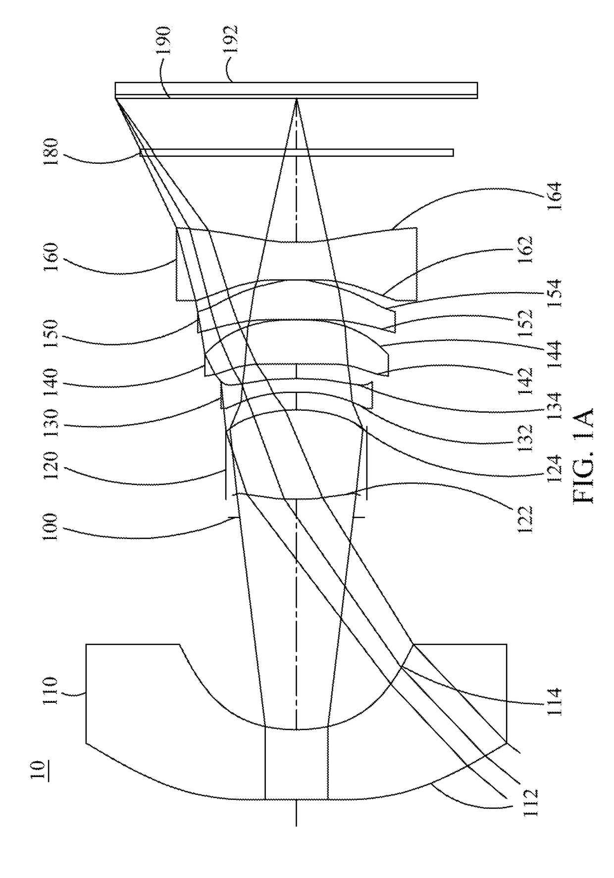
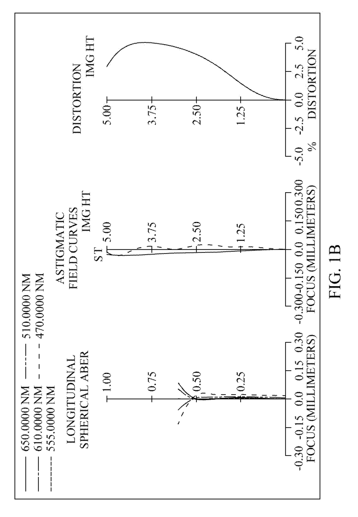
[0105]Please refer to FIG. 1A and FIG. 1B. FIG. 1A is a schematic view of the optical image capturing system according to the first embodiment of the present application, FIG. 1B is longitudinal spherical aberration curves, astigmatic field curves, and an optical distortion curve of the optical image capturing system in the order from left to right according to the first embodiment of the present application, and FIG. 1C is a lateral aberration diagram of tangential fan, sagittal fan, the longest operation wavelength and the shortest operation wavelength passing through an edge of the entrance pupil and incident on the image plane by 0.7 HOI according to the first embodiment of the present application. As shown in FIG. 1A, in order from an object side to an image side, the optical image capturing system includes a first lens element 110, an aperture stop 100, a second lens element 120, a third lens element 130, a fourth lens element 140, a fifth le...

second embodiment (embodiment 2)

The Second Embodiment (Embodiment 2)

[0167]Please refer to FIG. 2A, FIG. 2B and FIG. 2C, FIG. 2A is a schematic view of the optical image capturing system according to the second embodiment of the present application, FIG. 2B is longitudinal spherical aberration curves, astigmatic field curves, and an optical distortion curve of the optical image capturing system in the order from left to right according to the second embodiment of the present application, and FIG. 2C is a lateral aberration diagram of tangential fan, sagittal fan, the longest operation wavelength and the shortest operation wavelength passing through an edge of the entrance pupil and incident on the image plane by 0.7 HOI according to the second embodiment of the present application. As shown in FIG. 2A, in order from an object side to an image side, the optical image capturing system includes an aperture stop 200, a first lens element 210, a second lens element 220, a third lens element 230, a fourth lens element 24...

second embodiment

The detailed data of the optical image capturing system of the second embodiment is as shown in Table 3.

TABLE 3Data of the optical image capturing systemf = 5.707 mm; f / HEP = 1.6; HAF = 52.5 degFocalSurface #Curvature RadiusThicknessMaterialIndexAbbe #length0Object1E+181E+181Ape. stop1E+18−0.0362Lens 16.0362135740.518Plastic1.54555.9619.801313.243048450.00041E+180.2325Lens 2−62.642793640.844Plastic1.54555.967.6246−3.9238325970.1027Lens 370.090734140.375Plastic1.64222.46−9.62785.7134072080.4259Lens 45.4102976550.560Plastic1.54555.964185.470105.2247263740.66511Lens 5−4.8015794021.600Plastic1.54555.965.63712−2.0970318560.10013Lens 63.3053170371.267Plastic1.64222.46−10.827141.9080239091.12515IR-bandstop1E+180.500BK_71.51764.13filter161E+181.12017Image plane1E+180.000Reference wavelength (d-line) = 555 nm; shield position: The clear aperture of the fourth surface is 1.775 mm. The clear aperture of the fourteenth surface is 5.700 mm.

As for the parameters of the aspheric surfaces of the se...


PUM


Abstract

A six-piece optical lens for capturing image and a six-piece optical module for capturing image are provided. In order from an object side to an image side, the optical lens along the optical axis includes a first lens with refractive power, a second lens with refractive power, a third lens with refractive power, a fourth lens with refractive power, a fifth lens with refractive power and a sixth lens with refractive power. At least one of the image-side surface and object-side surface of each of the six lens elements is aspheric. The optical lens can increase aperture value and improve the imagining quality for use in compact cameras.

Description

CROSS-REFERENCE TO RELATED APPLICATION[0001]This application claims the benefit of Taiwan Patent Application No. 105104112, filed on Feb. 5, 2016, in the Taiwan Intellectual Property Office, the disclosure of which is incorporated herein in its entirety by reference.BACKGROUND OF THE INVENTION[0002]1. Field of the Invention[0003]The present disclosure relates to an optical image capturing system, and more particularly to a compact optical image capturing system which can be applied to electronic products.[0004]2. Description of the Related Art[0005]In recent years, with the rise of portable electronic devices having camera functionalities, the demand for an optical image capturing system is raised gradually. The image sensing device of ordinary photographing camera is commonly selected from charge coupled device (CCD) or complementary metal-oxide semiconductor sensor (CMOS Sensor). In addition, as advanced semiconductor manufacturing technology enables the minimization of pixel size...

Claims


Application Information

Patent Timeline
IPC IPC(8): G02B13/00G02B27/64G02B7/04G02B9/62G02B5/20
CPCG02B13/0045G02B9/62G02B5/20G02B13/003G02B27/646G02B5/208G02B7/04G02B13/0015G02B13/06
Inventor LAI, CHIEN-HSUNLIU, YAO-WEICHANG, YEONG-MING
Owner ABILITY OPTO ELECTRONICS TECH
Why Eureka
Try Eureka