Outsole for sports shoes

Inactive Publication Date: 2006-03-14
PUMA SE
View PDF18 Cites 12 Cited by
  • Summary
  • Abstract
  • Description
  • Claims
  • Application Information

AI Technical Summary

Benefits of technology

[0011]A primary object of the invention is achieved by the height of at least one cleat in the sole edge region of the heel region being reduced as compared to the average height of the other cleats in this region, all the cleats in this region lying

Problems solved by technology

Here, it has proved to be disadvantageous that above all with moderately hard ground, for example superficially frozen ground, contact between the foot and the ground is undesirably ha

Method used


Image

  • Outsole for sports shoes
  • Outsole for sports shoes
  • Outsole for sports shoes

Examples


Example

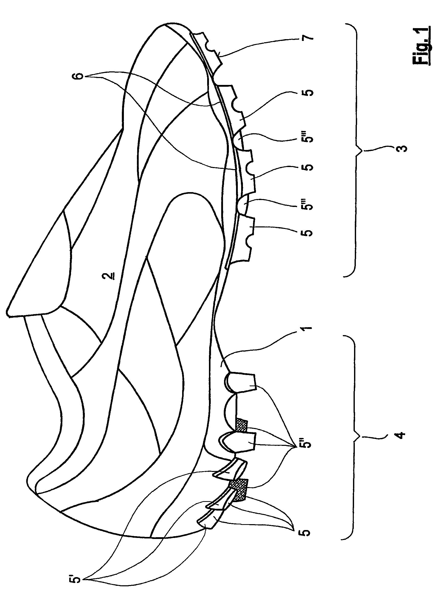
[0024]FIG. 1 shows a left athletic shoe 2 that has an outsole 1 on the underside of which are arranged a plurality of cleats 5, 5′, 5″, 5′″. The cleats 5 to 5′″ are injection molded in a common injection molding process when the outside 1 is injection molded, i.e., are molded onto the outsole 1.

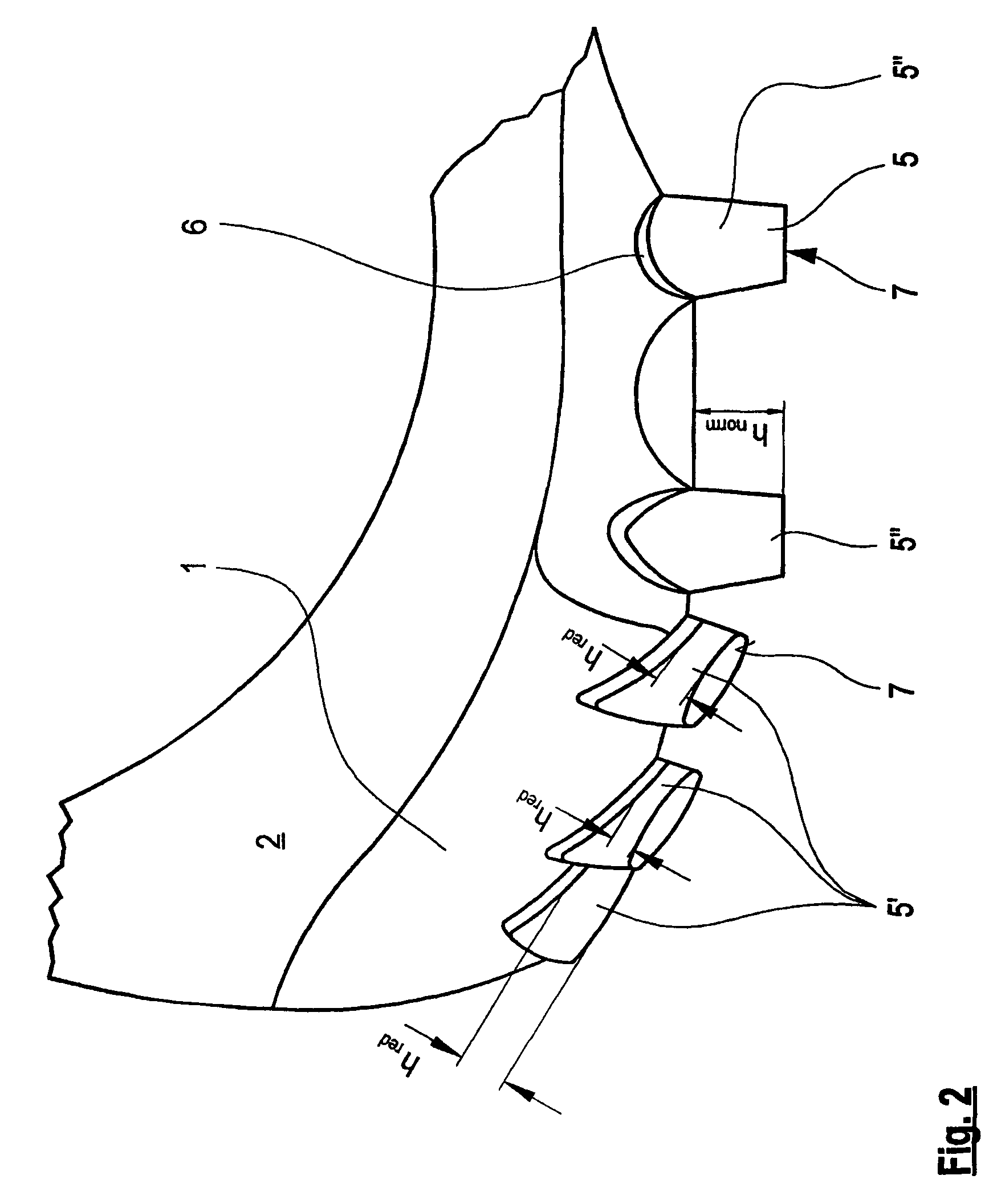
[0025]The cleats 5, 5′, 5″, 5′″ or a part thereof are arranged both in the front sole region 3 and in the heel region 4 of the outsole 1. These cleats have a base 6 from which they taper conically to their contact surface 7.

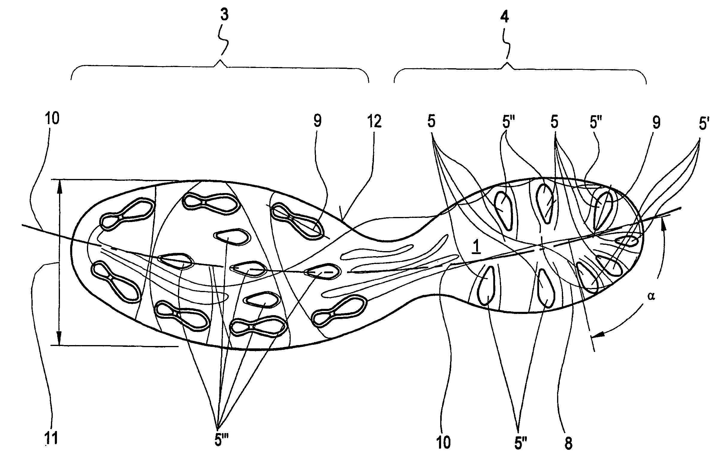
[0026]In cross-section, the cleats 5, 5′, 5″, 5′″, like the base 6, have an elongated shape, preferably an elliptical or roughly elliptical shape, as can be seen in FIG. 3. In the front sole region 3, cleats 5 are arranged along the sole edge region 12, the longitudinal axis 9 of which runs in the direction of the sole edge region 12. In contrast, in the heel region 4, the cleats 5 are arranged in the sole edge region 12 so that the longitudinal axis 9 of the cleats runs a...


PUM


Abstract

An outsole (1) for athletic shoes (2) having stud-type cleat elements arranged in the front sole area (3) and heel area (4), the cleat elements extending in a conically tapered manner from the base (6) thereof to the contact surface (7). To improve the outsole, in order to enable improved contact of the feet when they are placed on the ground, even when the ground is moderately hard, the height (hred) of at least one cleat element (5′) in the sole edge area (12) of the heel area (4) is reduced in relation to the average height (hnorm) of the other cleat elements (5″) in that area.

Description

BACKGROUND OF THE INVENTION[0001]1. Field of the Invention[0002]This application is a 371 of PCT / DE01 / 04431 Filed Nov. 21, 2001.[0003]The invention relates to an outsole for athletic shoes, in particular football shoes, with cleats tapering conically from their base to their contact surface and molded onto the front sole region and heel region of the sole.[0004]2. Description of Related Art[0005]An outsole of the kind described is known from published German Patent Application DE 37 03 932 A1. Here, cleats which protrude normally from the base geometry of the sole are molded to the sole by a common injection molding process through which the sole is also manufactured. With such cleats the result is a athletic shoe which exhibits good gripping properties, particularly on hard ground.[0006]A athletic shoe is known from German Patent Application DE 24 54 241 A which exhibits so-called sliding prevention profiling in the heel region. For this, provision is made for the portion of the so...

Claims


Application Information

Patent Timeline
IPC IPC(8): A43C15/08A43B13/22A43C15/00A43B13/26A43B5/02A43B13/14A43C15/02
CPCA43C15/02A43B5/02A43B13/14
Inventor SUSSMANN, REINHOLD
Owner PUMA SE
Why Eureka
Try Eureka