Web printer with dual print zones having opposing feed directions

Inactive Publication Date: 2011-02-24
ZAMTEC
View PDF20 Cites 12 Cited by
  • Summary
  • Abstract
  • Description
  • Claims
  • Application Information

AI Technical Summary

Benefits of technology

[0135]Flat upper and lower print zones reduce the overall height of the printer significantly. Furthermore, the flat media feed paths allow all the upper printheads to be flat relative to each other and all the lower printheads to

Problems solved by technology

Producing the plates and aligning the various drums for registration of each color, and for correct registration of the print of both sides of the web, is exceptionally time consuming—usually several hours.
For short print runs—say less than 1000 copies—web printing becomes uneconomical.
This reduces the time and

Method used


Image

  • Web printer with dual print zones having opposing feed directions
  • Web printer with dual print zones having opposing feed directions
  • Web printer with dual print zones having opposing feed directions

Examples


Embodiment Construction

Overview

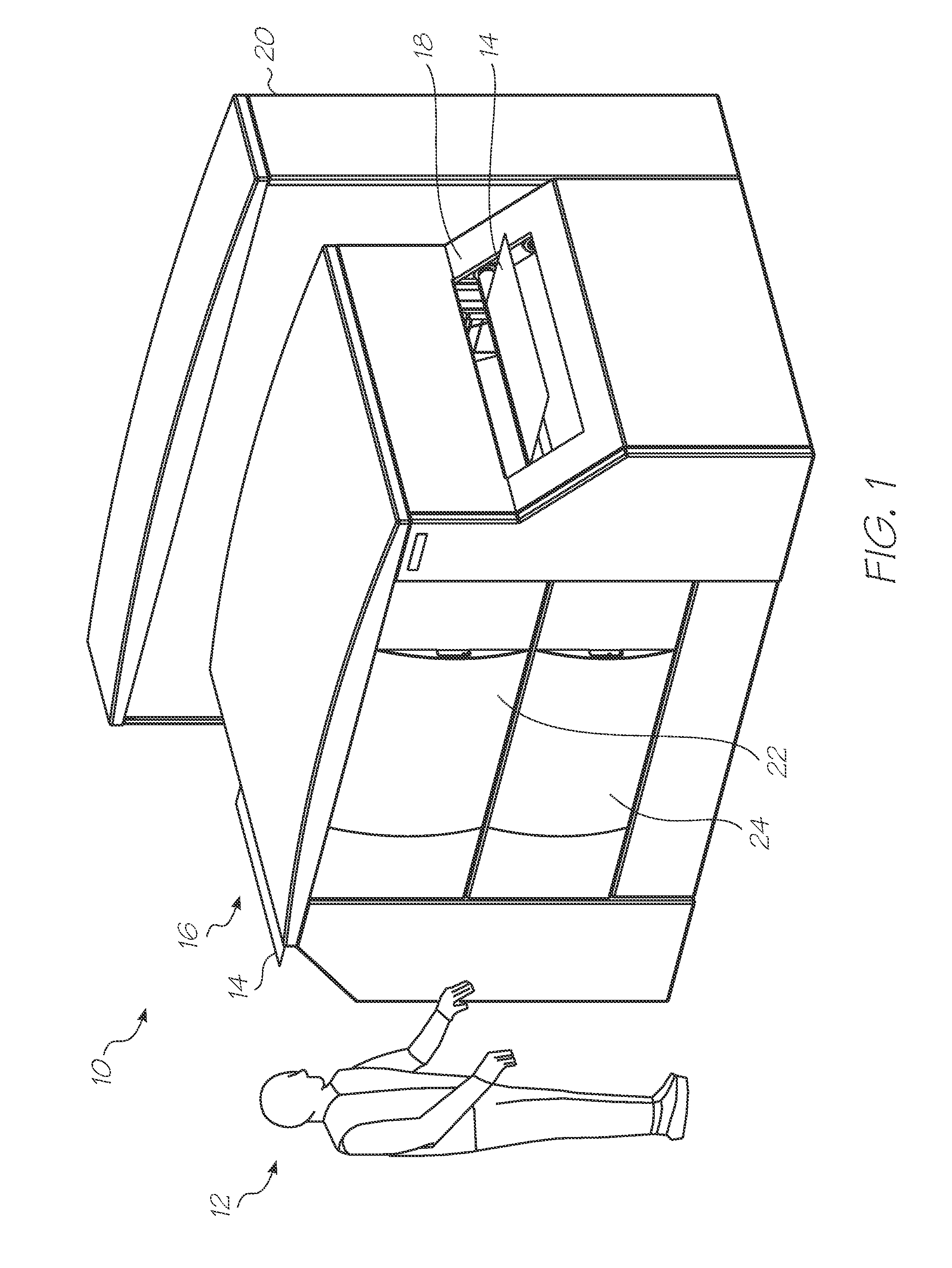
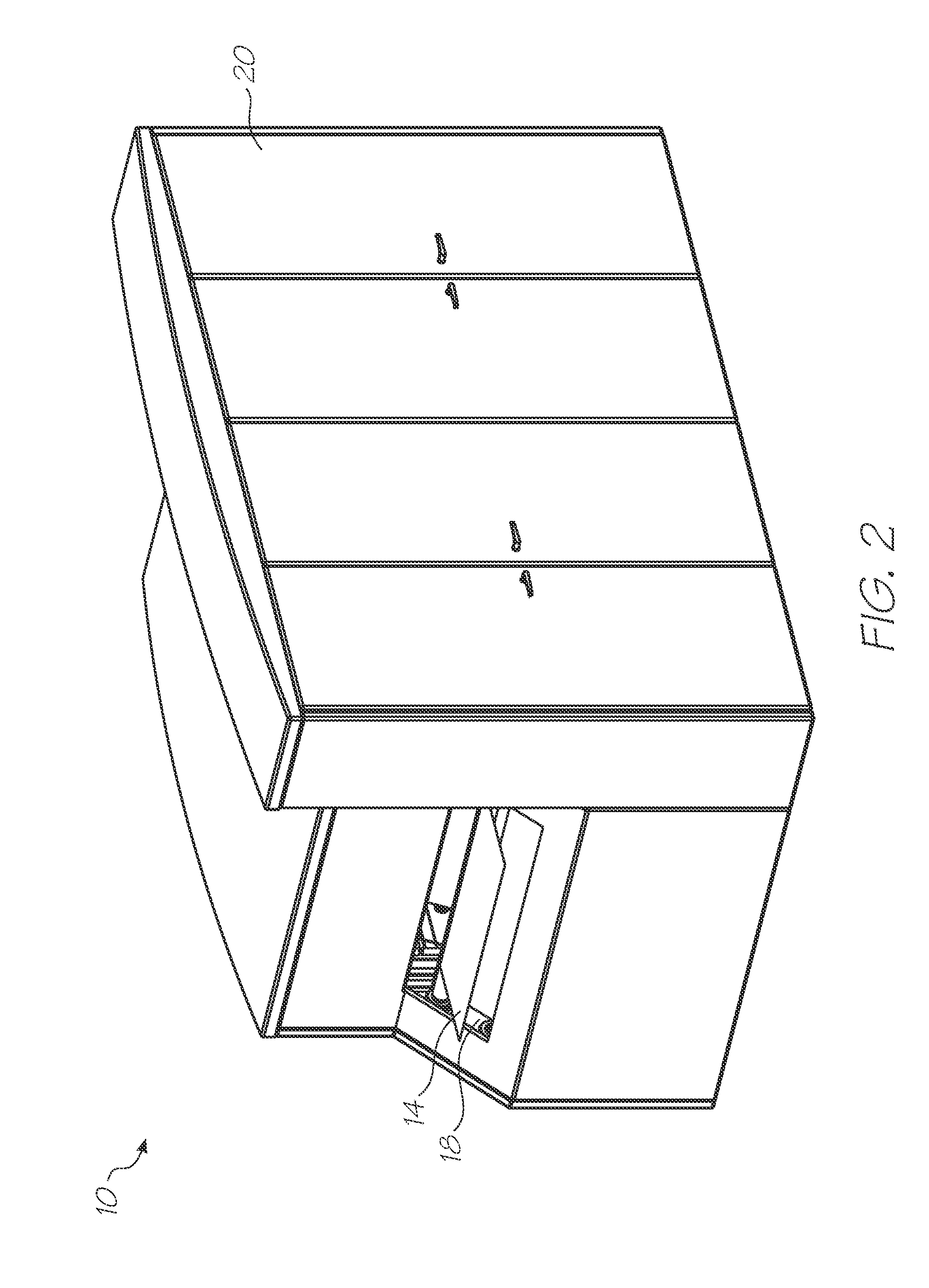
[0179]FIG. 1 shows the continuous web printer 10 next to a person 12 for context as to the printer size and footprint. A continuous web of media 14 is fed from a web roll unwinder (not shown) into the web inlet 16, through the printer 10 to the web outlet 18 where it is collected by a web roll winder (not shown). Web winders and unwinders are widely used and well known in the industry (see for example U.S. Pat. No. 5,178,341). On the front of the printer 10 are two removable panels 22 and 24 concealing the upper and lower printhead assembly drawers (described below). FIG. 2 shows the ink tanks and control processor storage cabinets 20 at the rear of the printer 10.

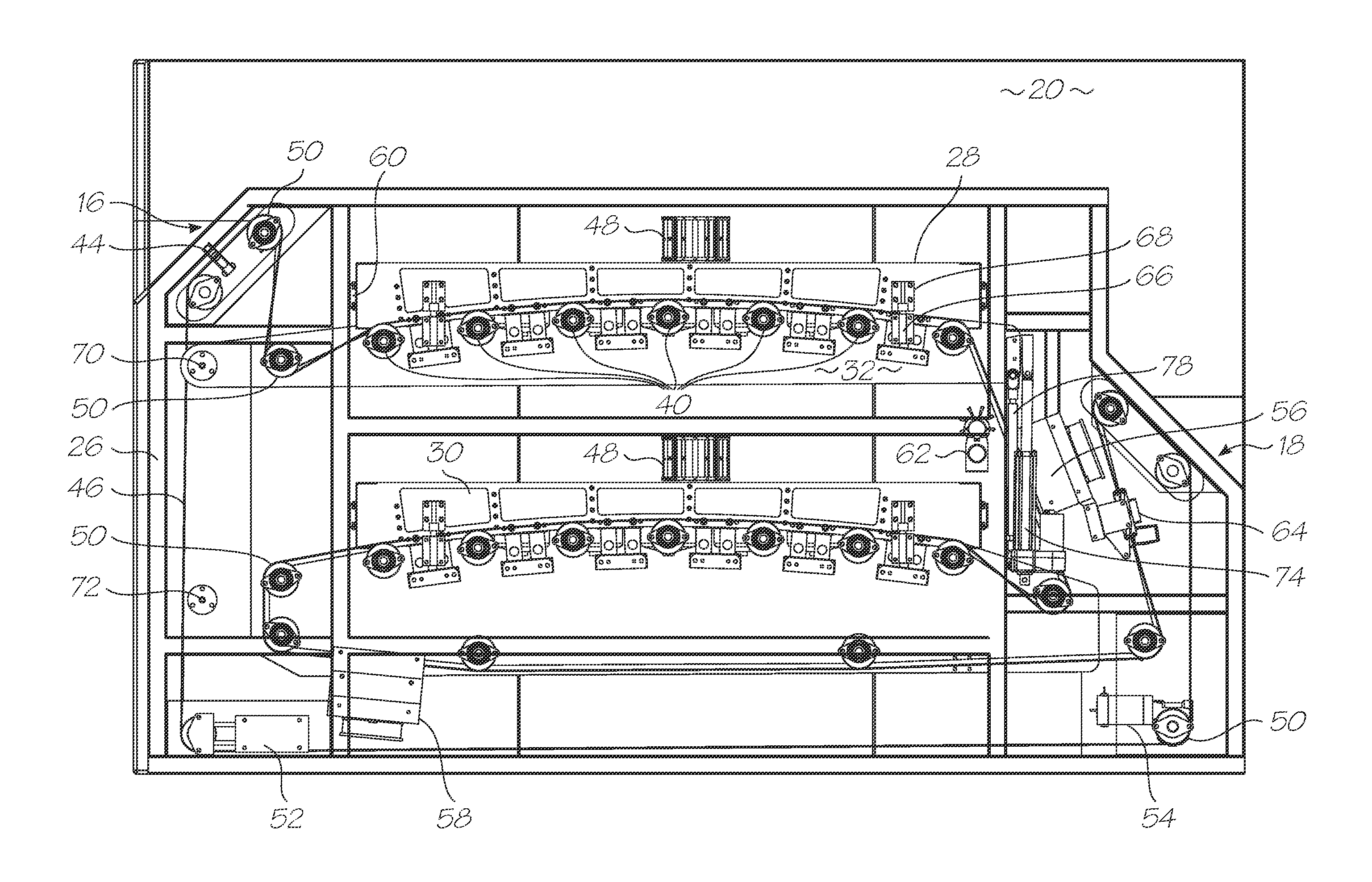
[0180]FIG. 3 shows the interior of the printer 10 with the outer paneling removed. The printer chassis 26 supports an upper printhead drawer 28 and a lower printhead draw 30. The upper printhead drawer 28 prints on the first side 36 of the media web 14 and the lower printhead drawer prints on the second side 38 of ...


PUM


Abstract

A continuous web printer that has an inlet for receiving a web of media from a media web roll unwinder, an outlet for delivery to a media web roll winder, a media feed path extending from the inlet to the outlet and pagewidth inkjet printhead assemblies positioned adjacent the media feed path for printing on both sides of the web. The media feed path has a first print zone positioned adjacent a second print zone. The first print zone is a section of the media feed path in which one side of the web is printed. The second print zone is a section of the media feed path in which the other side of the web is printed. During use the web is fed along the media feed path in a feed direction, the feed direction in the first print zone is opposed to the feed direction in the second print zone.

Description

FIELD OF THE INVENTION[0001]The invention relates to printing long rolls of media, or ‘web’ as it is known. In particular, the invention relates to inkjet printing of continuous web as opposed to individual sheets of media substrate.CO-PENDING APPLICATIONS[0002]The following applications have been filed by the Applicant simultaneously with the present application:MWB001US MWB003US MWB004US MWB005US MWB006US MWB007US MWB008US[0003]The disclosures of these co-pending applications are incorporated herein by reference. The above applications have been identified by their filing docket number, which will be substituted with the corresponding application number, once assigned.BACKGROUND OF THE INVENTION[0004]Web printers are used for very high volume print runs, say greater 1000 copies but could well be more than 1 million copies for newspapers and the like. Traditionally, web printers use offset printing where plates embossed with the images and / or text are mounted on large drums that ro...

Claims


Application Information

Patent Timeline
IPC IPC(8): B41J2/01
CPCB41J3/60B41J15/04B41J29/17B41J29/377B41J2/16585B41J29/02
Inventor SILVERBROOK, KIAPROFACA, MARKSTRUDWICKE, CRAIG DONALDTHELANDER, JASON MARK
Owner ZAMTEC
Why Eureka
Try Eureka