Apparatus for changing optical disks

Inactive Publication Date: 2005-10-25
QUANTA STORAGE INC
View PDF2 Cites 12 Cited by
  • Summary
  • Abstract
  • Description
  • Claims
  • Application Information

AI Technical Summary

Benefits of technology

[0011]It is therefore an object of the invention to provide an apparatus for changing optical disks. Elastic devices are designed to urge trays or disks in the range of upright regions of driving shafts to stay close to each other, and hence the height of each driving shaft can be reduced in the case that the number of the trays or disks is not increased

Problems solved by technology

Moreover, owing to the incline of the thread 114, the tray or the disk held at the middle thread region 116b cannot be

Method used


Image

  • Apparatus for changing optical disks
  • Apparatus for changing optical disks
  • Apparatus for changing optical disks

Examples


Example

EXAMPLE 1

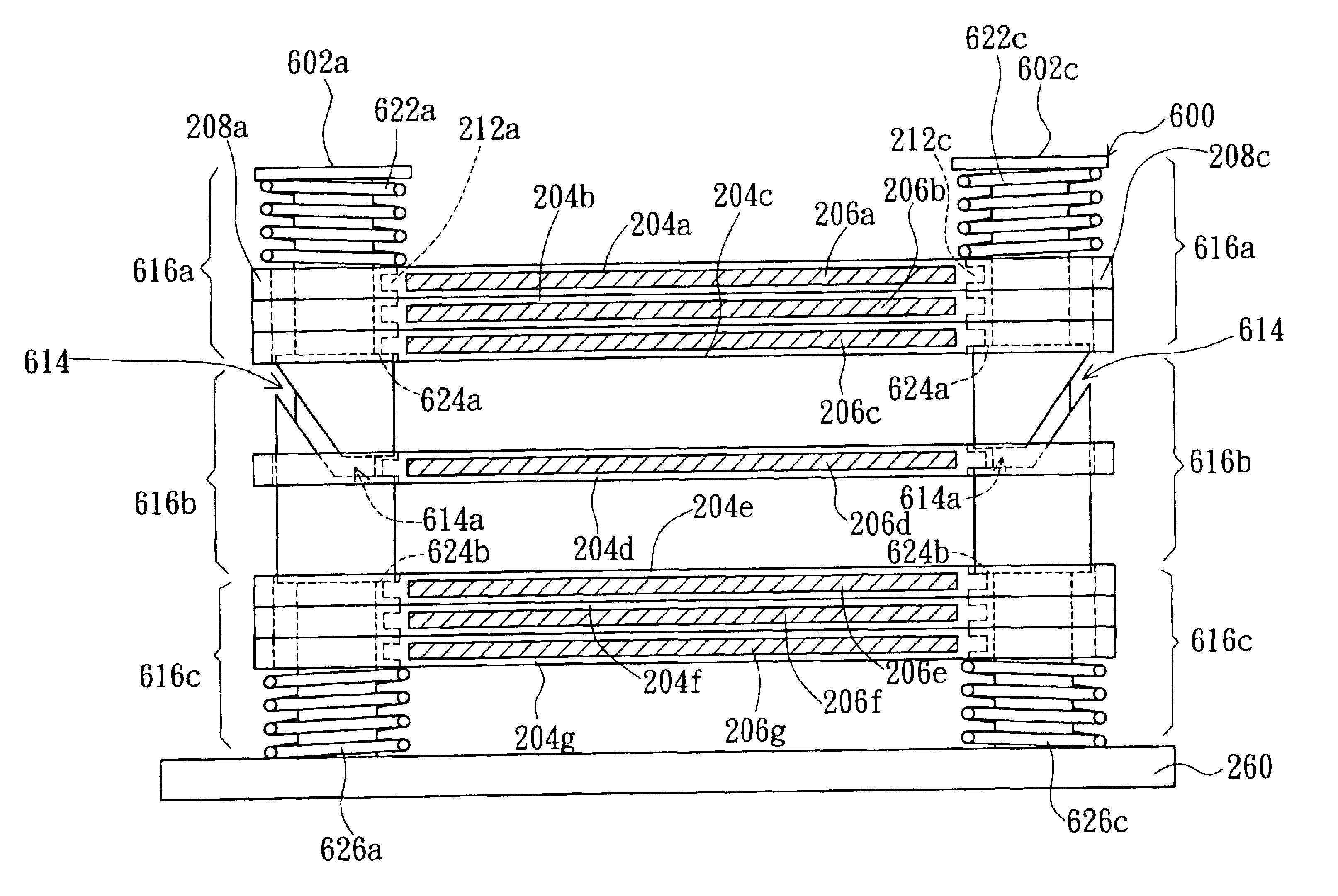
[0026]FIG. 2A shows a top view of the optical disk changer in Example 1 according to a preferred embodiment of the invention, and FIG. 2B shows a partial enlarged lateral view of the optical disk changer in FIG. 2A. As shown in FIG. 2A and FIG. 2B, the optical disk changer 200, mounted on a bottom plate 260 of an optical disk drive, includes at least driving shafts 202a, 202b (not shown in FIG. 2B), and 202c for clamping disk trays 204a, 204b, 204c, 204d, 204e, and 204f. These trays 204a-204f can be raised or lowered to position at different heights by rotating the driving shafts 202a, 202b, and 202c synchronously. The trays 204a-204f are provided for respectively holding disks 206a, 206b, 206c, 206d, 206e, and 206f (only the tray 204a and the disk 206a are shown in FIG. 2A), each of which has a round hole 250 at its center.

[0027]In FIG. 2A, there are projecting portions 208a, 208b, and 208c on the outer edge of the tray 204a. The line connecting the projecting portions 208...

Example

EXAMPLE 2

[0034]Referring to FIG. 3, a partial lateral view of the optical disk changer in Example 2 according to a preferred embodiment of the invention is shown. The difference between the optical disk changer 300 in this example and that in apparatus 200 in Example 1 lies in the optical disk changer 300 including at least elastic plates 322a, 322b (not shown in the figure), and 322c instead of coil springs 222a, 222b, and 222c. The elastic plates 322a and 322c are respectively located near the driving shafts 202a and 202c, each of which has one end fixed to the top plate 270 of the optical disk drive. In FIG. 3, as trays 204a-204f are carried from the position held at the thread region 216b to that held at the upright region 216a by rotating the driving shafts 202a and 202c, they will be clamped between the other end of the elastic plate 322a or 322c and the flat surface 224 of the corresponding driving shaft 202a or 202c. Conversely, trays 204a-204f can be forced by elastic plate...

Example

EXAMPLE 3

[0036]Referring to FIG. 4, a partial lateral view of the optical disk changer in Example 3 according to a preferred embodiment of the invention is shown. The optical disk changer 400 includes at least three driving shafts, and the related positions between the three driving shafts, trays, and optical disks are the same as those in FIG. 2A.

[0037]In FIG. 4, the optical disk changer 400, mounted on the bottom plate 260 of an optical disk drive, includes at least driving shafts 402a, 402c, and a driving shaft not shown in the figure, for clamping disk trays 204a-204f. These trays 204a-204f can be raised and lowered to position at different heights by rotating the driving shafts 402a and 402c synchronously. The trays 204a-204f are provided for correspondingly holding disks 206a-206f, and the structure of the trays 204a-204f are the same as shown in FIG. 2A and FIG. 2B.

[0038]The driving shafts 402a and 402c, respectively inserted into the inserting holes 210a and 210c of the tray...


PUM


Abstract

An apparatus for changing optical disks including a plurality of driving shafts, supported on the bottom plate of an optical disk drive, and a plurality of elastic devices. The driving shafts rotate synchronously around their vertical axes to raise and lower the trays. Each of the driving shafts includes a thread region, threads of which can be engaged with the trays, and an upright region located on the thread region. The pitch for threads in the upper thread portion is larger than that in the lower thread portion of the thread region. Each of the elastic devices has one end fixed to a top end of the upright region of the corresponding driving shaft or fixed beneath the top plate, and the other end provided together with the flat surface between the upright region and the thread region for clamping the trays in the range of the upright regions. Trays are also forced by the elastic devices by rotating the driving shafts to move along the thread from the position held at the upright region to that held at the thread region.

Description

[0001]This application claims the benefit of Taiwan application Serial No. 92108746, filed Apr. 15, 2003.BACKGROUND OF THE INVENTION[0002]1. Field of the Invention[0003]The invention relates in general to an apparatus for changing optical disks, and more particularly to an apparatus for changing optical disk with incorporated elastic devices.[0004]2. Description of the Related Art[0005]Nowadays, as technology develops and changes with each passing day, and pictures, music, movies and computer software are applied more and more widely, optical disks with the advantages of large capacity, small volume, and secure data storage have become the predominant software loading tool. As a result, an optical disk drive, capable of reading optical disks and designed to simultaneously hold a number of disks in an optical disk drive, has become an essential PC peripheral. By means of the optical disk changer, a particular optical disk can be easily selected and read by the pick-up head of the opt...

Claims


Application Information

Patent Timeline
IPC IPC(8): G11B21/08G11B15/68G11B17/03G11B7/085G11B17/26
CPCG11B17/26
Inventor PENG, WEN-KUAN
Owner QUANTA STORAGE INC
Why Eureka
Try Eureka