Antenna device and communication terminal apparatus

a technology of communication terminal and antenna device, which is applied in the field of antenna device, can solve the problems of significant lowering of antenna characteristics, and achieve the effects of enhancing magnetic field coupling, excellent communication characteristics, and efficient magnetic flux collection

Active Publication Date: 2017-09-28
MURATA MFG CO LTD
View PDF2 Cites 19 Cited by
  • Summary
  • Abstract
  • Description
  • Claims
  • Application Information

AI Technical Summary

Benefits of technology

[0008]Preferred embodiments of the present invention provide ring-shaped antenna devices with excellent communication characteristics and a simple configuration without using a large-sized antenna coil, and communication terminal apparatuses including the antenna devices.

Problems solved by technology

Moreover, when the arm of the ring, which incorporates therein the linear conductor, is made of metal, the arm made of metal shields a magnetic field, resulting in significant lowering in antenna characteristics.

Method used


Image

  • Antenna device and communication terminal apparatus
  • Antenna device and communication terminal apparatus
  • Antenna device and communication terminal apparatus

Examples


first preferred embodiment

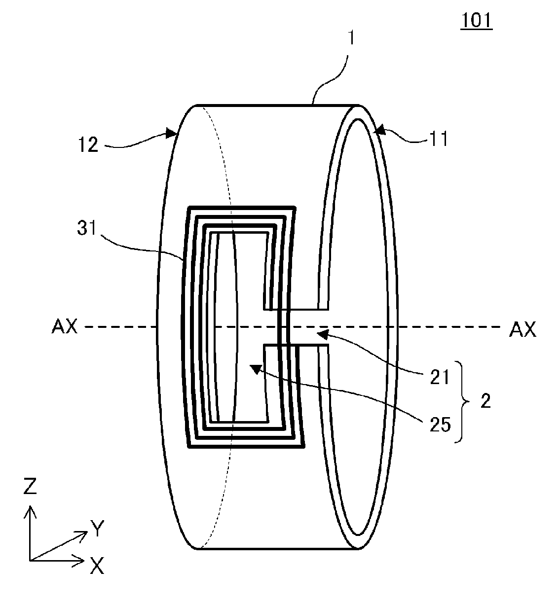
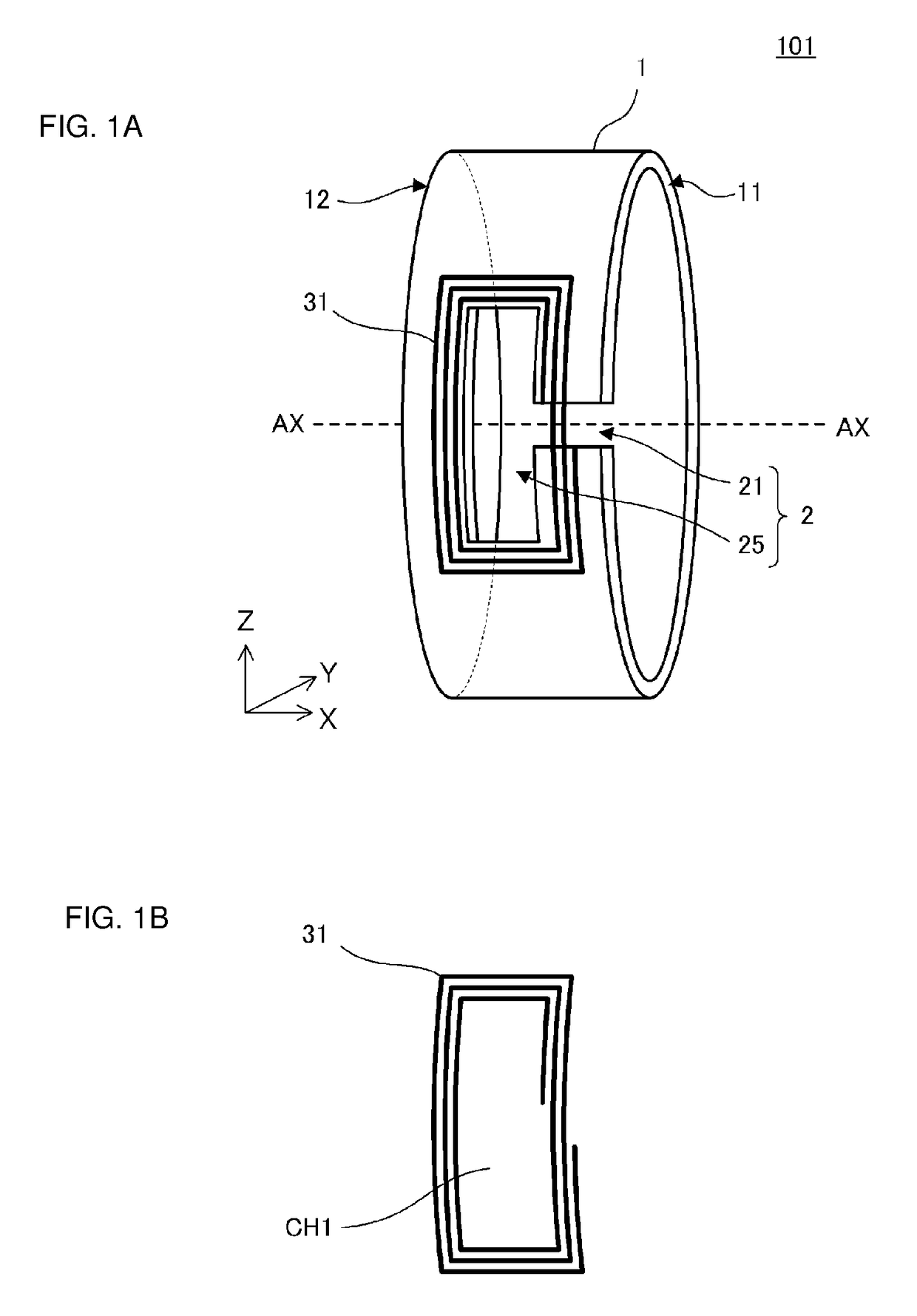
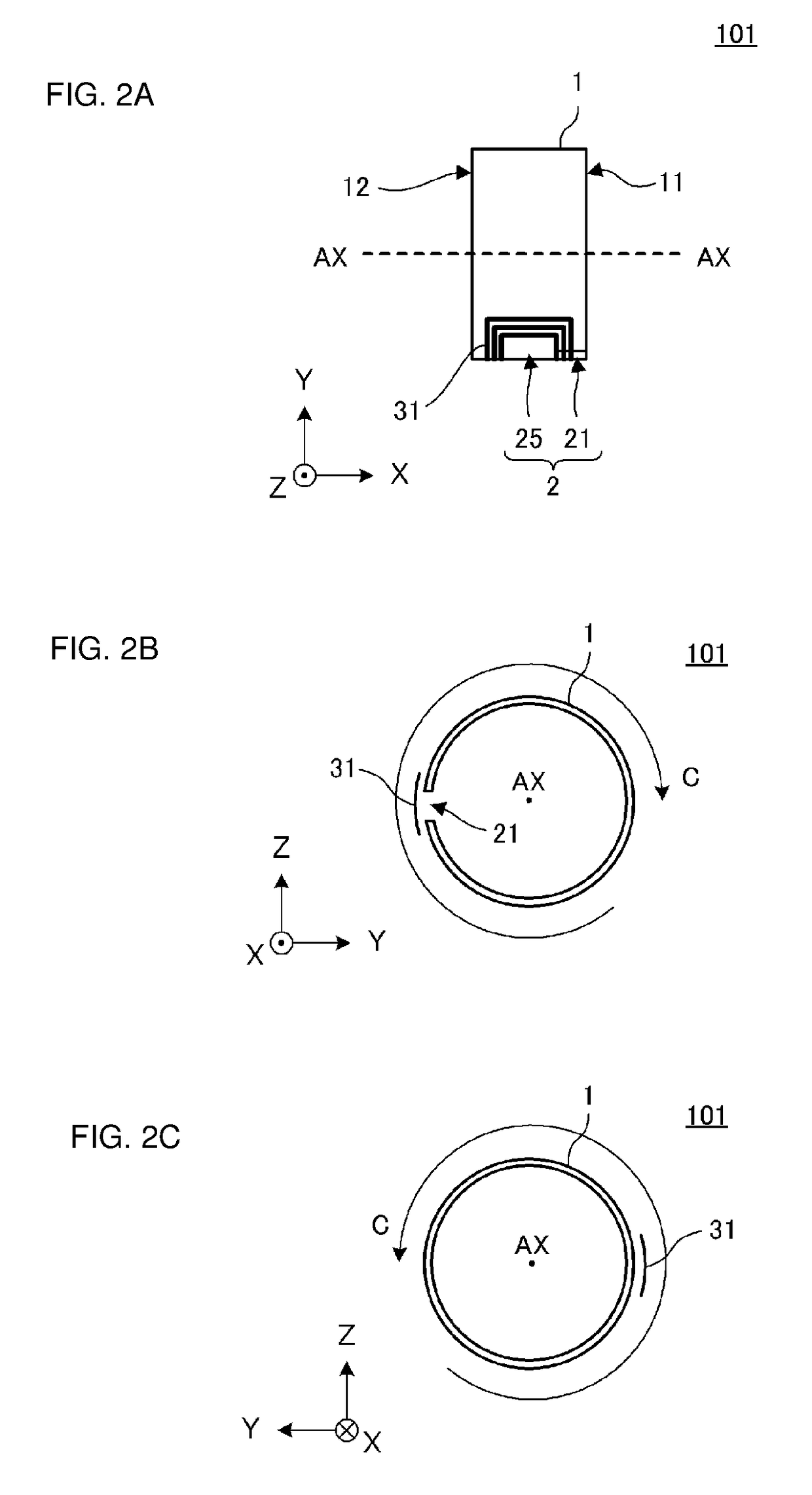
[0033]FIG. 1A is an outer appearance perspective view of an antenna device 101 according to a first preferred embodiment of the present invention and FIG. 1B is a plan view of a conductor pattern of a power feed coil 31 included in the antenna device 101. FIG. 2A is a plan view of the antenna device 101, FIG. 2B is a right side view of the antenna device 101, and FIG. 2C is a left side view of the antenna device 101. FIG. 1 and FIG. 2 illustrate the configuration of the antenna device 101 in a simplified manner to make the drawings and the principle more clear.

[0034]The antenna device 101 preferably includes a ring-shaped conductor 1 and a power feed coil 31.

[0035]The ring-shaped conductor 1 is a conductor preferably with a ring shape, which is arranged about an axis AX, and includes a first edge end portion 11 and a second edge end portion 12 that are perpendicular or substantially perpendicular to an axial direction (X direction in FIG. 2A). The ring-shaped conductor 1 includes a ...

second preferred embodiment

[0057]FIG. 5 is an outer appearance perspective view of an antenna device 102 according to a second preferred embodiment of the present invention. FIG. 5 illustrates the structure of the antenna device 102 in a simplified manner.

[0058]The antenna device 102 in the second preferred embodiment is different from the antenna device 101 in the first preferred embodiment in a point that a cavity has no wide portion and has a single constant width, that is, in a shape of a power feed coil when seen from the radial direction. Other configurations thereof are preferably the same or substantially the same as those of the antenna device 101 in the first preferred embodiment.

[0059]Hereinafter, elements of the antenna device 102, which are different from the antenna device 101 in the first preferred embodiment, will be described.

[0060]As illustrated in FIG. 5, the cavity in the antenna device 102 does not include a wide portion and instead includes only a slit portion 22 that is inward from the ...

third preferred embodiment

[0063]FIG. 6 is an outer appearance perspective view of an antenna device 103 according to a third preferred embodiment of the present invention. FIG. 6 illustrates the configuration of the antenna device 103 in a simplified manner.

[0064]The antenna device 103 in the third preferred embodiment is different from the antenna device 101 in the first preferred embodiment in a point that the antenna device 103 further includes a slit portion 23. Other configurations thereof preferably are the same or substantially the same as those of the antenna device 101 in the first preferred embodiment.

[0065]Hereinafter, elements of the antenna device 103, which are different from the antenna device 101 in the first preferred embodiment, will be described.

[0066]A cavity in the antenna device 103 preferably includes the slit portion 23 inward (to the right side in FIG. 6) from the second edge end portion 12 in addition to the slit portion 21 and the wide portion 25. As illustrated in FIG. 6, the cavi...


PUM


Abstract

An antenna device includes a power feed coil and a ring-shaped conductor arranged about an axis and a ring-shaped conductor including first and second edge end portions in an axial direction and a cavity inward from the first edge end portion. At least a portion of the cavity overlaps with a coil opening of the power feed coil when seen from the radial direction. The power feed coil causes electric field coupling, magnetic field coupling, and / or electromagnetic field coupling with the cavity. The ring-shaped conductor defines and functions as a booster antenna of the power feed coil. A substantial coil opening defining and functioning as an antenna is larger than that when only the power feed coil is provided, thus facilitating coupling with a communication partner-side antenna coil.

Description

CROSS REFERENCE TO RELATED APPLICATIONS[0001]This application claims the benefit of priority to Japanese Patent Application No. 2015-028105 filed on Feb. 16, 2015 and is a Continuation Application of PCT Application No. PCT / JP2015 / 086170 filed on Dec. 25, 2015. The entire contents of each application are hereby incorporated herein by reference.BACKGROUND OF THE INVENTION[0002]1. Field of the Invention[0003]The present invention relates to an antenna device, and in particular, relates to an antenna device included in, for example, a wearable terminal. Furthermore, the present invention relates to a communication terminal apparatus, and in particular, relates to a communication terminal apparatus that is used as, for example, a wearable terminal.[0004]2. Description of the Related Art[0005]In recent years, various ring-shaped communication terminal apparatuses such as finger rings, arm rings, and wristwatches, which are directly wearable by a human, have been devised. The communicatio...

Claims


Application Information

Patent Timeline
Patent Type & Authority Applications(United States)
IPC IPC(8): G06K19/077H01Q9/04H01Q7/08G06K19/07
CPCG06K19/07701H01Q7/08H01Q9/04G06K19/0725G06K19/0723G06K19/077G06K19/07762
Inventor TOKUNAGA, TSUYOSHIWANG, JIAN
Owner MURATA MFG CO LTD
Why Eureka
Try Eureka