
Power amplification module and front end circuit

a technology of power amplification module and front end circuit, which is applied in the direction of transmission, multi-port network, high frequency amplifier, etc., can solve the problems of affecting the reception circuit side receiving sensitivity, harmonic distortion generating noise, and reducing the reception sensitivity of the reception circuit side, so as to achieve excellent communication characteristics, high isolation, and excellent communication characteristics

Active Publication Date: 2018-11-13
MURATA MFG CO LTD
View PDF24 Cites 0 Cited by
  • Summary
  • Abstract
  • Description
  • Claims
  • Application Information

AI Technical Summary

Benefits of technology

The present disclosure aims to provide a power amplification module that can achieve excellent communication performance in a range of multiple communication bands. The disclosure also includes a front end circuit that utilizes this power amplification module. This patent enables the realization of seamless communication in different regions, enhancing the overall quality of communication.

Problems solved by technology

In general, in amplification of a transmission signal with a power amplifier, heat is generated and harmonic distortion occurs to generate noise.
This noise includes reception band noise having a frequency within a reception band.
The reception band noise that enters the reception circuit side degrades receiving sensitivity.
However, when the reception band noise is intended to be sufficiently attenuated with the duplexers, the transmission signal may possibly be attenuated more than necessary.

Method used


Image

  • Power amplification module and front end circuit
  • Power amplification module and front end circuit
  • Power amplification module and front end circuit

Examples


first embodiment

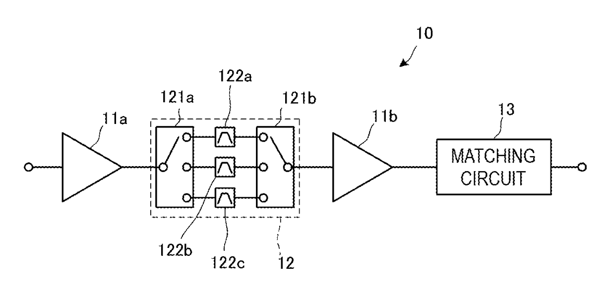
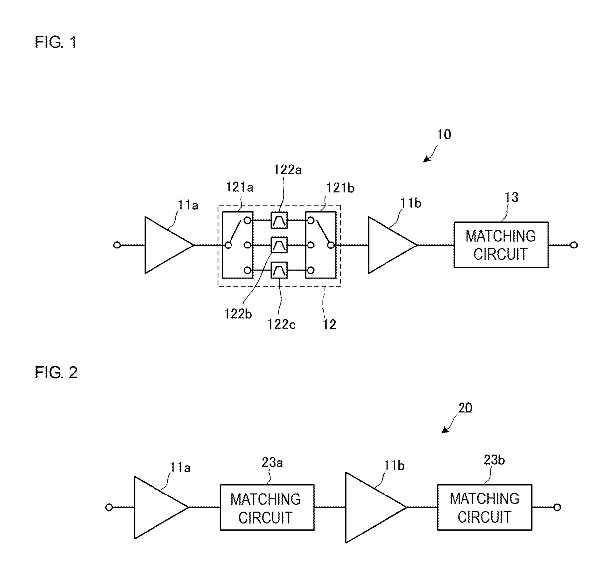
[0040]A power amplifier (PA) module 10 according to the present disclosure will now be described. The PA module 10 corresponds to a power amplification module of the present disclosure. FIG. 1 is a diagram illustrating the configuration of the PA module 10. The PA module 10 includes amplifying elements 11a and 11b, a variable filter circuit 12, and a matching circuit 13. An input terminal of the amplifying element 11a is connected to an input terminal of the PA module 10. An output terminal of the amplifying element 11a is connected to an input terminal of the variable filter circuit 12. An output terminal of the variable filter circuit 12 is connected to an input terminal of the amplifying element 11b. An output terminal of the amplifying element 11b is connected to an output terminal of the PA module 10 with the matching circuit 13 interposed therebetween.

[0041]Each of the amplifying elements 11a and 11b is a multimode-multiband power amplifier capable of being used in multiple co...

second embodiment

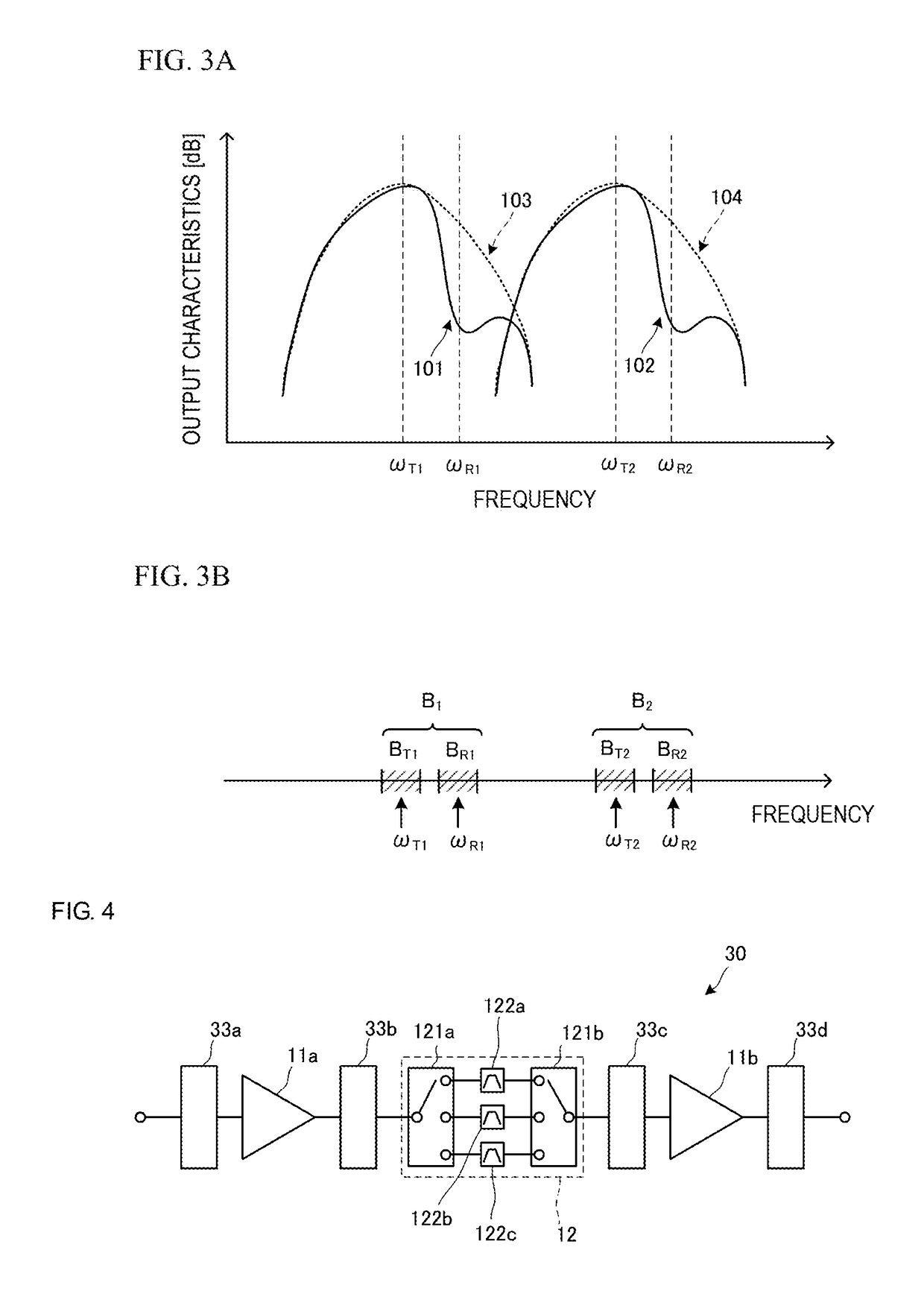
[0060]A PA module 30 according to the present disclosure will now be described. FIG. 4 is a diagram illustrating the configuration of the PA module 30. A wide-band matching circuit 33a is connected between an input terminal of the PA module 30 and the input terminal of the amplifying element 11a. A wide-band matching circuit 33b is connected between the output terminal of the amplifying element 11a and the input terminal of the variable filter circuit 12. A wide-band matching circuit 33c is connected between the output terminal of the variable filter circuit 12 and the input terminal of the amplifying element 11b. A wide-band matching circuit 33d is connected between the output terminal of the amplifying element 11b and an output terminal of the PA module 30. A temperature sensor (not illustrated) is provided near the PA module 30. The temperature sensor is used to correct the changes in impedance of the amplifying elements 11a and 11b and the variable filter circuit 12, which are c...

third embodiment

[0081]In the third embodiment, as described above, only the transmission modulation band that is used, in the transmission band, is used as the pass band of the variable filter circuit. Specifically, the pass band of the variable filter circuit is narrowed down not in accordance with the entire transmission band that is used but in accordance with the transmission modulation band that is used. This improves bandpass characteristics of the variable filter circuit and increases the effect of attenuating the reception band noise.

>


PUM


Abstract

A PA module (10) includes multiple amplifying elements (11a, 11b) and a variable filter circuit (12). The amplifying elements (11a, 11b) amplify a transmission signal in a frequency range including multiple communication bands and are cascade-connected to each other. The variable filter circuit (12) is connected between the amplifying elements (11a, 11b). The variable filter circuit (12) uses a transmission band corresponding to a used communication band selected from the multiple communication bands as a pass band and a reception band corresponding to the used communication band as an attenuation band.

Description

BACKGROUND OF THE DISCLOSURE[0001]Field of the Disclosure[0002]The present disclosure relates to a power amplification module that amplifies a transmission signal and a front end circuit including the power amplification module.[0003]Description of the Related Art[0004]Front end circuits in related art are disclosed in, for example, Patent Document 1. The front end circuit described in Patent Document 1 includes a wide-band power amplifier, a band switch, and duplexers. The wide-band power amplifier is a multimode-multiband power amplifier. The multiple duplexers are provided for the respective communication bands. The wide-band power amplifier is connected to the duplexers with the band switch interposed therebetween.[0005]In transmission in a certain communication band, a transmission signal amplified by the wide-band power amplifier is supplied to the duplexer corresponding to the communication band through the band switch. The duplexer causes the transmission signal to be transm...

Claims


Application Information

Patent Timeline
Patent Type & Authority Patents(United States)
IPC IPC(8): H03F1/02H04B1/04H03F3/21H03H7/38H04B1/525H03F3/19H03F3/24H03F1/56
CPCH03F1/0205H03F1/565H03F3/19H03F3/211H03F3/245H03H7/38H04B1/525H04B1/04H04B2001/0416H03F2200/111H03F2200/318H03F2200/411H03F2203/21139
Inventor HITOMI, SHINYAOBIYA, HIDENORISATO, TSUYOSHIYANAGIHARA, SHINGO
Owner MURATA MFG CO LTD
Learn More