Front-end circuit
a front-end circuit and circuit technology, applied in the field of front-end circuits, can solve the problems of possible likely deterioration of reception characteristics, and achieve the effects of excellent reception characteristics, less likely to deterioration, and good reception characteristics
- Summary
- Abstract
- Description
- Claims
- Application Information
AI Technical Summary
Benefits of technology
Problems solved by technology
Method used
Image
Examples
first embodiment
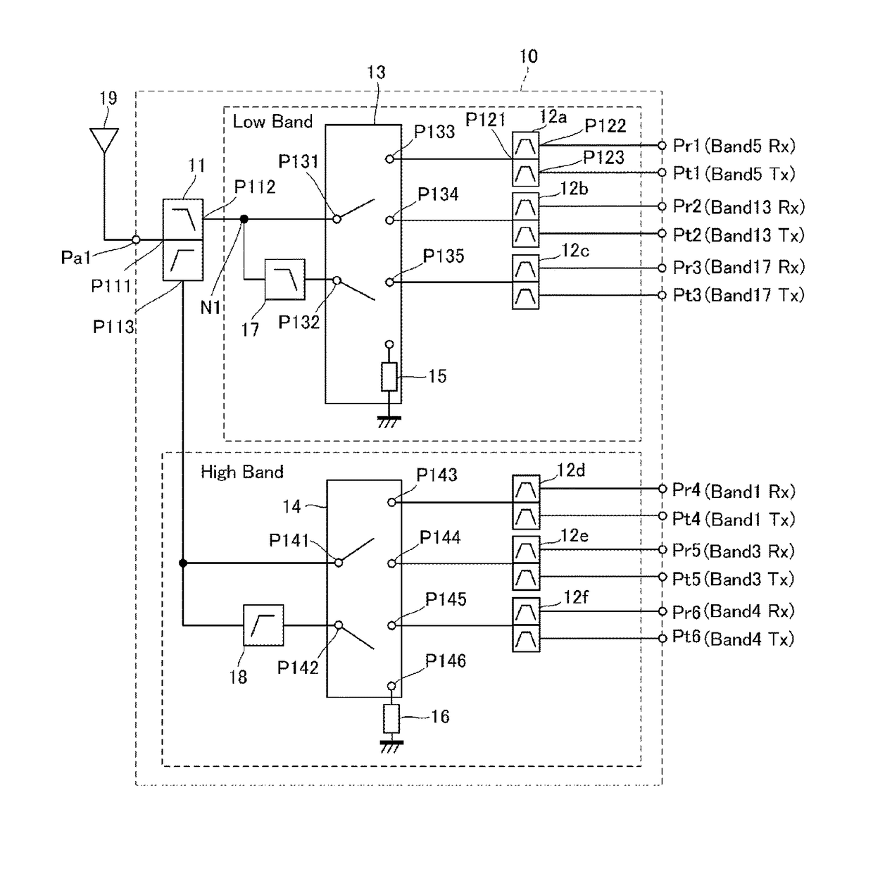
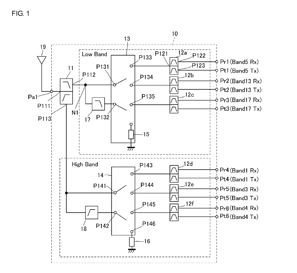
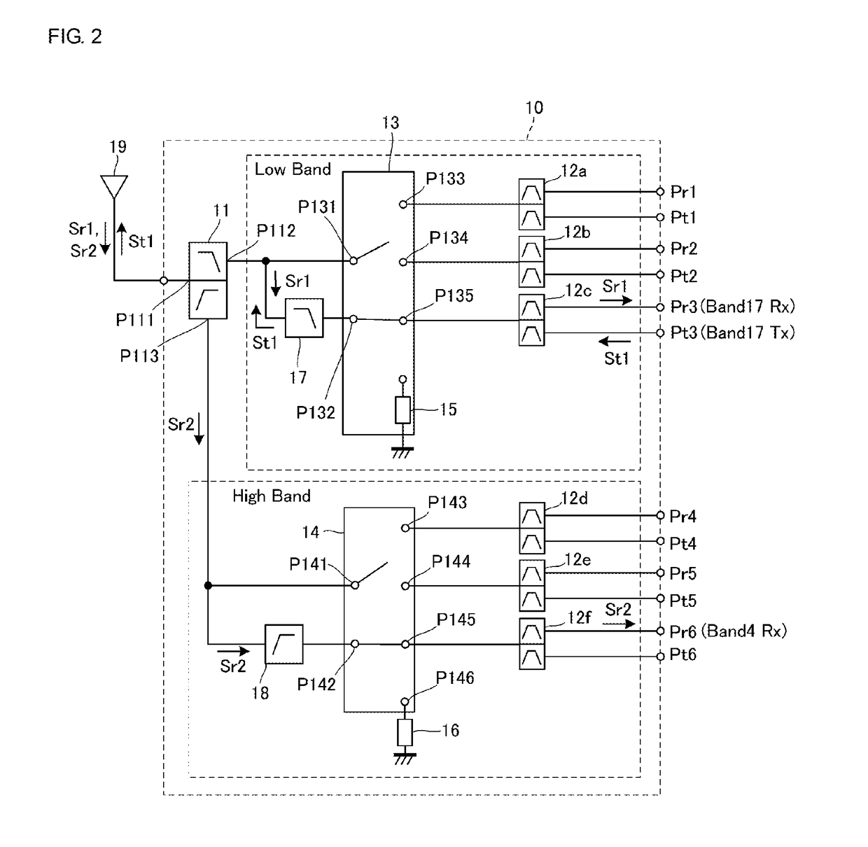
[0034]A front-end circuit according to a first embodiment of the present disclosure will be described. FIG. 1 is a block diagram illustrating a front-end circuit 10 according to the first embodiment. The front-end circuit 10 includes an antenna port Pa1, transmission ports Pt1 to Pt6, and reception ports Pr1 to Pr6. The antenna port Pa1 is connected to an antenna 19. The transmission ports Pt1 to Pt6 are connected to a transmission circuit (not illustrated). The reception ports Pr1 to Pr6 are connected to a reception circuit (not illustrated).
[0035]Each of the transmission ports Pt1 to Pt3 corresponds to a first transmission port according to the present disclosure. Each of the transmission ports Pt4 to Pt6 corresponds to a second transmission port according to the present disclosure. Each of the reception ports Pr1 to Pr3 corresponds to a first reception port according to the present disclosure. Each of the reception ports Pr4 to Pr6 corresponds to a second reception port according...
second embodiment
[0080]A front-end circuit according to a second embodiment of the present disclosure will now be described. FIG. 6 is a block diagram illustrating a front-end circuit 30 according the second embodiment. The front-end circuit 30 has the configuration according to the first embodiment, and in addition, includes a duplexer 31, switching circuits 32a and 32b, band-pass filters 33a to 33f, an antenna port Pa2, and reception ports Pr7 to Pr12.
[0081]The duplexer 31 includes one common terminal and two individual terminals and separates a communication signal of the low band and a communication signal of the high band from each other. Each of the switching circuits 32a and 32b includes one common terminal and three to-be-selected terminals. The reception ports Pr7 to Pr9 correspond to the low band. The reception ports Pr10 to Pr12 correspond to the high band.
[0082]The antenna port Pa2 is connected to an antenna 34. The reception ports Pr7 to Pr12 are connected to a reception circuit (not il...
third embodiment
[0085]A front-end circuit according to a third embodiment of the present disclosure will now be described. FIG. 7 is a block diagram illustrating a portion of a front-end circuit 40 according to the third embodiment. The front-end circuit 40 includes a switching circuit 43 instead of the switching circuit 13 according to the first embodiment. The front-end circuit 40 has the configuration according to the first embodiment, and in addition, includes a low-pass filter 41 and an impedance element 42.
[0086]The switching circuit 43 is a triple-pole, triple-throw (3P3T) switch and includes the common terminals P131 and P132, a common terminal P431, and the to-be-selected terminals P133 to P135. The common terminal P431 of the switching circuit 43 is connected to the connection point N1 with the low-pass filter 41 interposed therebetween. The impedance elements 15 and 42 are disposed in the switching circuit 43. The common terminal P132 of the switching circuit 43 is connected to one of th...
PUM
 Abstract
Description
Claims
Application Information
 - R&D
- Intellectual Property
- Life Sciences
- Materials
- Tech Scout
- Unparalleled Data Quality
- Higher Quality Content
- 60% Fewer Hallucinations
Browse by: Latest US Patents, China's latest patents, Technical Efficacy Thesaurus, Application Domain, Technology Topic, Popular Technical Reports.
© 2025 PatSnap. All rights reserved.Legal|Privacy policy|Modern Slavery Act Transparency Statement|Sitemap|About US| Contact US: help@patsnap.com


