Antenna device and electronic appliance

a technology of electronic appliances and antenna devices, applied in the direction of resonant antennas, antenna earthings, transmission, etc., can solve the problems of increasing the difficulty of securing a space in which to mount antenna devices in cellular phone terminals, degrading antenna characteristics, and large conductor loss, and achieve excellent communication characteristics

Active Publication Date: 2018-08-21
MURATA MFG CO LTD
View PDF7 Cites 0 Cited by
  • Summary
  • Abstract
  • Description
  • Claims
  • Application Information

AI Technical Summary

Benefits of technology

[0009]Accordingly, preferred embodiments of the present invention provide an antenna device that is configured such that, when the antenna device is built into an electronic appliance equipped with a display device in which a conductor layer is arranged, communication is performed with excellent communication characteristics from a display surface side of the display device, and provide an electronic appliance that includes the antenna device.

Problems solved by technology

However, as the bodies of cellular phone terminals become smaller and the degree of integration of cellular phone terminals becomes ever higher, it is becoming increasingly difficult to secure a space in which to mount an antenna device in cellular phone terminals.
In such a case, there is a problem in that the antenna characteristics are degraded by unwanted coupling between the antenna device and the metal plate when the antenna device is arranged close to the display device.
Consequently, conductor loss is large and excellent antenna characteristics cannot be obtained when an antenna is formed of a transparent electrode such as an ITO electrode as described in Japanese Unexamined Patent Application Publication No. 2006-195802.

Method used


Image

  • Antenna device and electronic appliance
  • Antenna device and electronic appliance
  • Antenna device and electronic appliance

Examples


first preferred embodiment

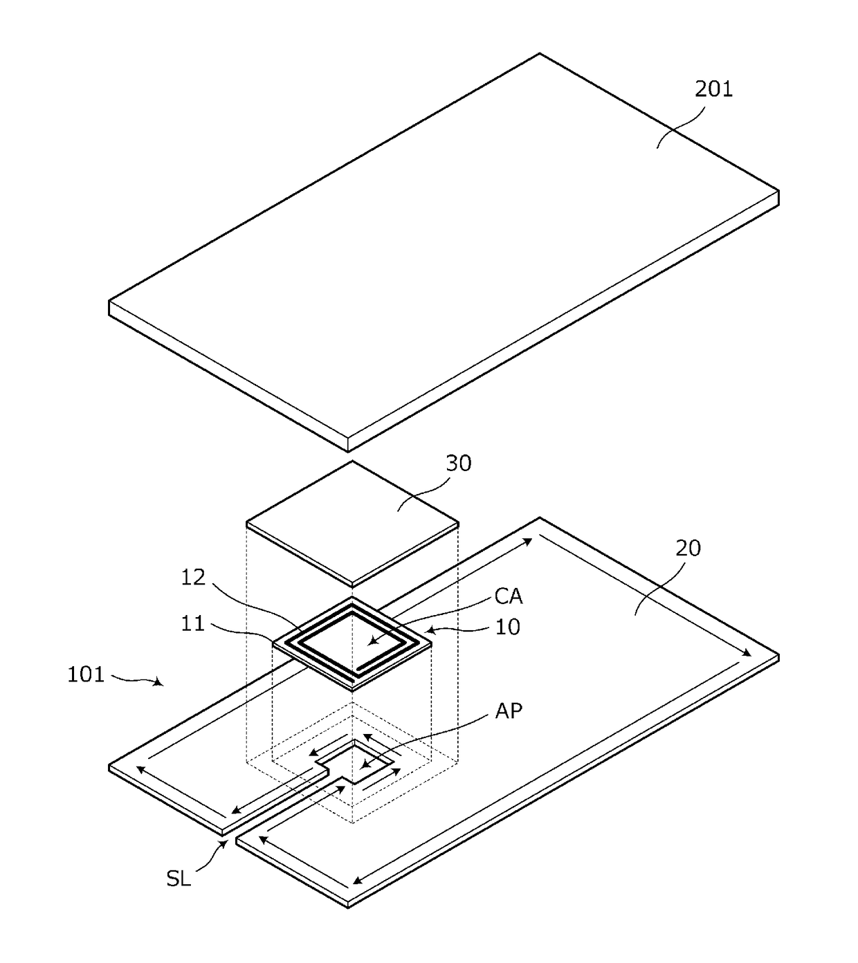
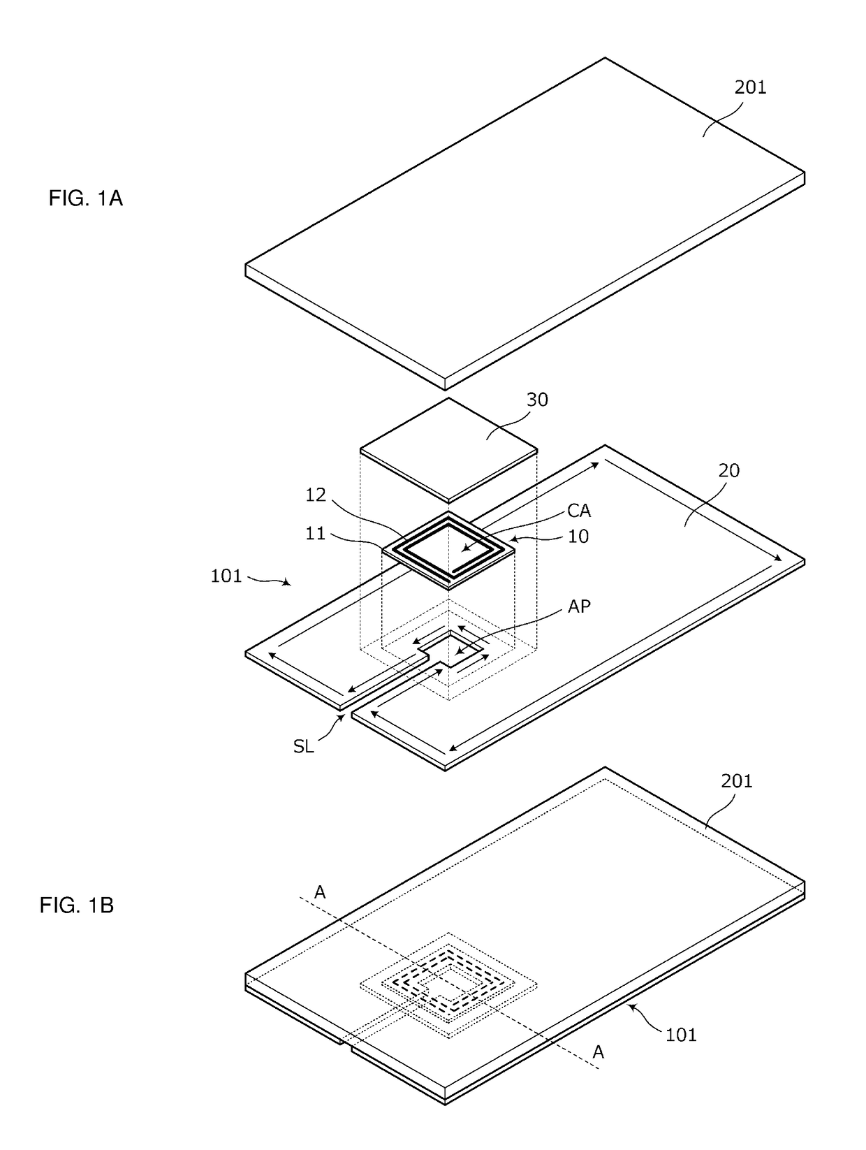
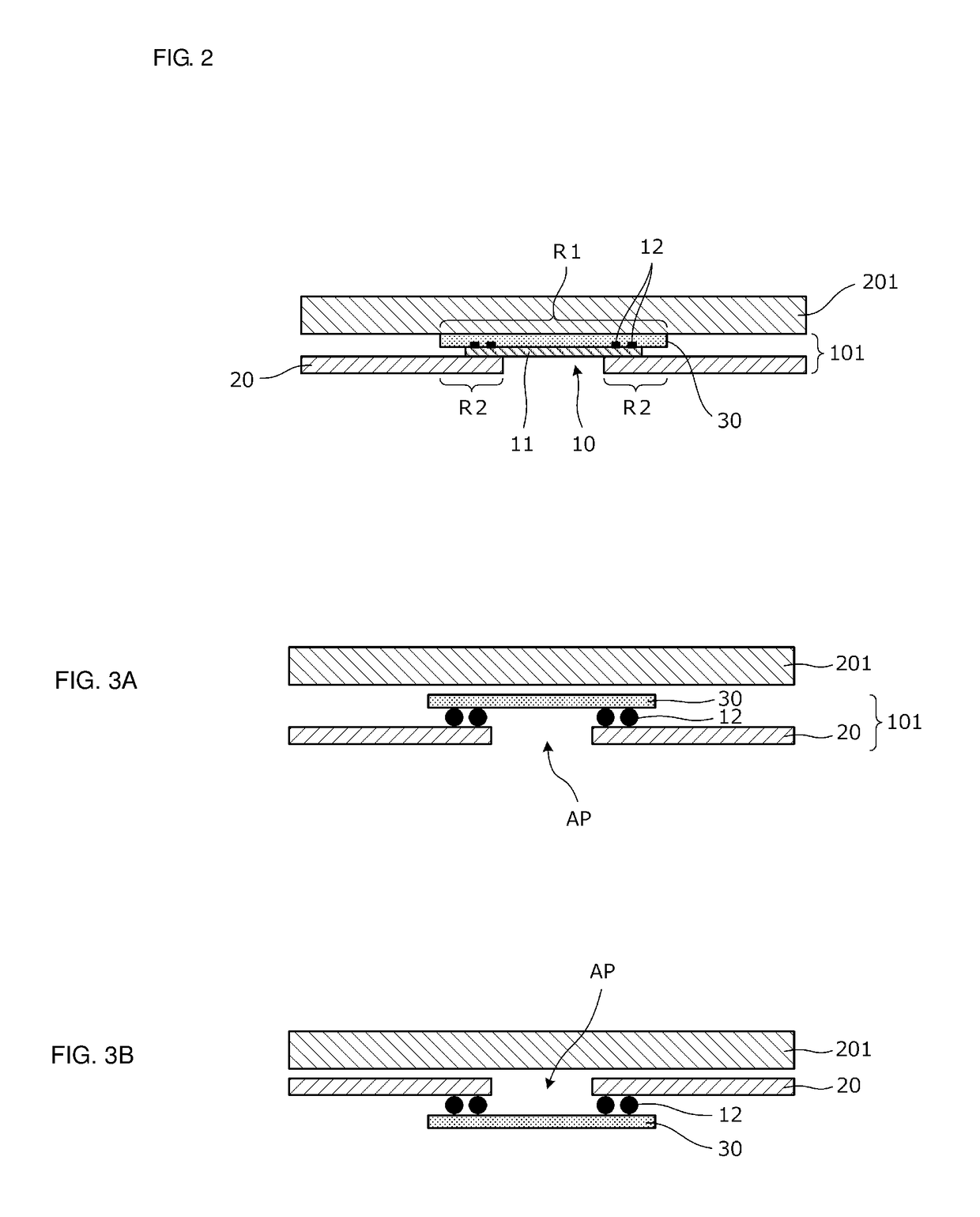
[0036]FIG. 1A is an exploded perspective view of the main portion of an electronic appliance that includes an antenna device according to a first preferred embodiment of the present invention, the antenna device being close to a display device, and FIG. 1B is a perspective view of a state where the display device and the antenna device are stacked one on top the other. In addition, FIG. 2 is a sectional view taken along A-A in FIG. 1B.

[0037]An antenna device 101 of this preferred embodiment is arranged on a side of a display device 201 (hereafter referred to as “rear surface side”) that is opposite to a display surface side of the display device 201. The antenna device 101 includes a planar conductor 20, power feeding coil 10 and a magnetic sheet 30. An upper surface of the display device 201, in the state illustrated in FIGS. 1A and 1B, is a display surface of the display device 201.

[0038]The display device 201 is an organic EL display or a liquid crystal display and conductive mem...

second preferred embodiment

[0072]FIG. 6 is a sectional view of an electronic appliance 302 according to a second preferred embodiment of the present invention. The electronic appliance 302 includes a casing 50, the display device 201, the power feeding coil 10, the magnetic sheet 30, the planar conductor 20 and the circuit board 40.

[0073]In contrast to the configuration illustrated in FIG. 2 etc. in the first preferred embodiment, the power feeding coil 10 is arranged on the lower surface of the planar conductor 20 (surface on opposite side to display device 201). A power feeding circuit is provided on the circuit board 40. The power feeding circuit is connected to the two ends of the coil conductor 12 via spring pin terminals 41.

[0074]In the configuration illustrated in FIG. 6 as well, unwanted coupling between the coil conductor 12 of the power feeding coil 10 and the display device 201 is significantly reduced or prevented by the magnetic sheet 30.

[0075]In this preferred embodiment, it is easy to connect t...

third preferred embodiment

[0076]FIG. 7 is a sectional view of an electronic appliance 303 according to a third preferred embodiment of the present invention. The electronic appliance 303 includes the casing 50, the display device 201, the magnetic sheet 30, the planar conductor 20 and the circuit board 40.

[0077]In contrast to the first and second preferred embodiments, the coil conductor 12 of the power feeding coil is provided in a non-ground region NGR of the circuit board 40. The coil conductor 12 is preferably defined by a rectangular or substantially rectangular spiral-shaped pattern, for example. In addition, a power feeding circuit that is connected to the coil conductor 12 is provided on the circuit board 40.

[0078]In this preferred embodiment, the number of components is reduced and assembly is easy.


PUM


Abstract

An antenna device includes a planar conductor on a side of a display device that is opposite to a display surface side of the display device and a power feeding coil including a spiral-shaped coil conductor with a coil aperture at a center thereof. The planar conductor includes a cutout portion. The coil aperture of the power feeding coil is superposed with the cutout portion of the planar conductor in plan view. A magnetic sheet that is superposed with the coil conductor in plan view is arranged between the display device and the planar conductor and between the display device and the power feeding coil.

Description

CROSS REFERENCE TO RELATED APPLICATIONS[0001]This application claims the benefit of priority to Japanese Patent Application 2014-088927 filed on Apr. 23, 2014 and is a Continuation Application of PCT / JP2015 / 062035 filed on Apr. 21, 2015. The entire contents of each application are hereby incorporated by reference.BACKGROUND OF THE INVENTION[0002]1. Field of the Invention[0003]The present invention relates to antenna devices preferably for use in near field communication (NFC) systems and so forth and to communication appliances equipped with such an antenna device.[0004]2. Description of the Related Art[0005]It is becoming increasingly common for NFC systems to be incorporated into small-sized electronic appliances such as cellular phone terminals and tablet PCs. In particular, in the case of a cellular phone terminal, an NFC antenna is demanded with which communication can be performed in a state where a display surface of the cellular phone terminal is made to face an antenna devi...

Claims


Application Information

Patent Timeline
Patent Type & Authority Patents(United States)
IPC IPC(8): H01Q1/24H01Q1/48H01Q9/28H04B5/00H01Q13/10H01Q7/00H01Q1/38
CPCH01Q1/24H01Q1/241H01Q1/38H04B5/0031H01Q7/00H01Q9/285H01Q13/10H01Q1/48
Inventor NAKANO, SHINICHI
Owner MURATA MFG CO LTD
Why Eureka
Try Eureka