Modular lighting system

a technology of modular lighting and lighting components, applied in the direction of lighting, lighting and heating equipment protection devices, semiconductor devices for light sources, etc., can solve the problems of known modular systems and present difficulties in assembly, and achieve the effect of simple manufacturing and assembly

Active Publication Date: 2017-10-12
ARTEMIDE
View PDF6 Cites 7 Cited by
  • Summary
  • Abstract
  • Description
  • Claims
  • Application Information

AI Technical Summary

Benefits of technology

[0007]It is therefore an object of the present invention to provide a modular lighting system,, which is particularly simple to make and assemble, and which offers a wide variety of different configurations, also three-dimensional (in other words extending not only in two directions but in three directions).

Problems solved by technology

Furthermore, the known modular systems can, at times, present difficulties related to their assembly, also requiring the use of tools.

Method used


Image

  • Modular lighting system
  • Modular lighting system
  • Modular lighting system

Examples


Embodiment Construction

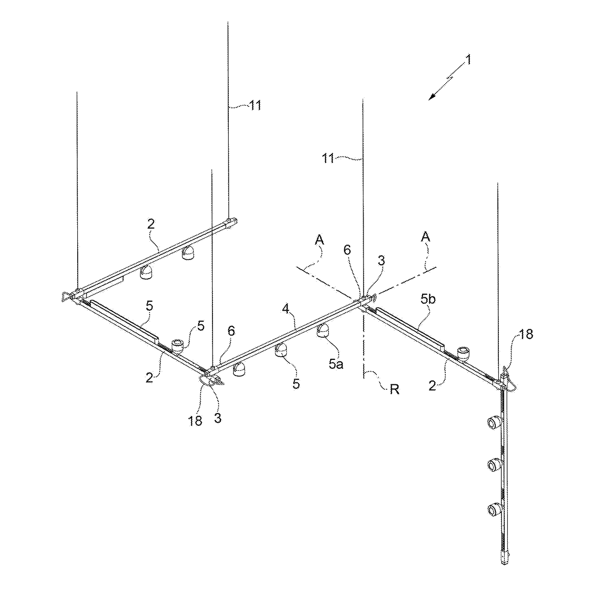
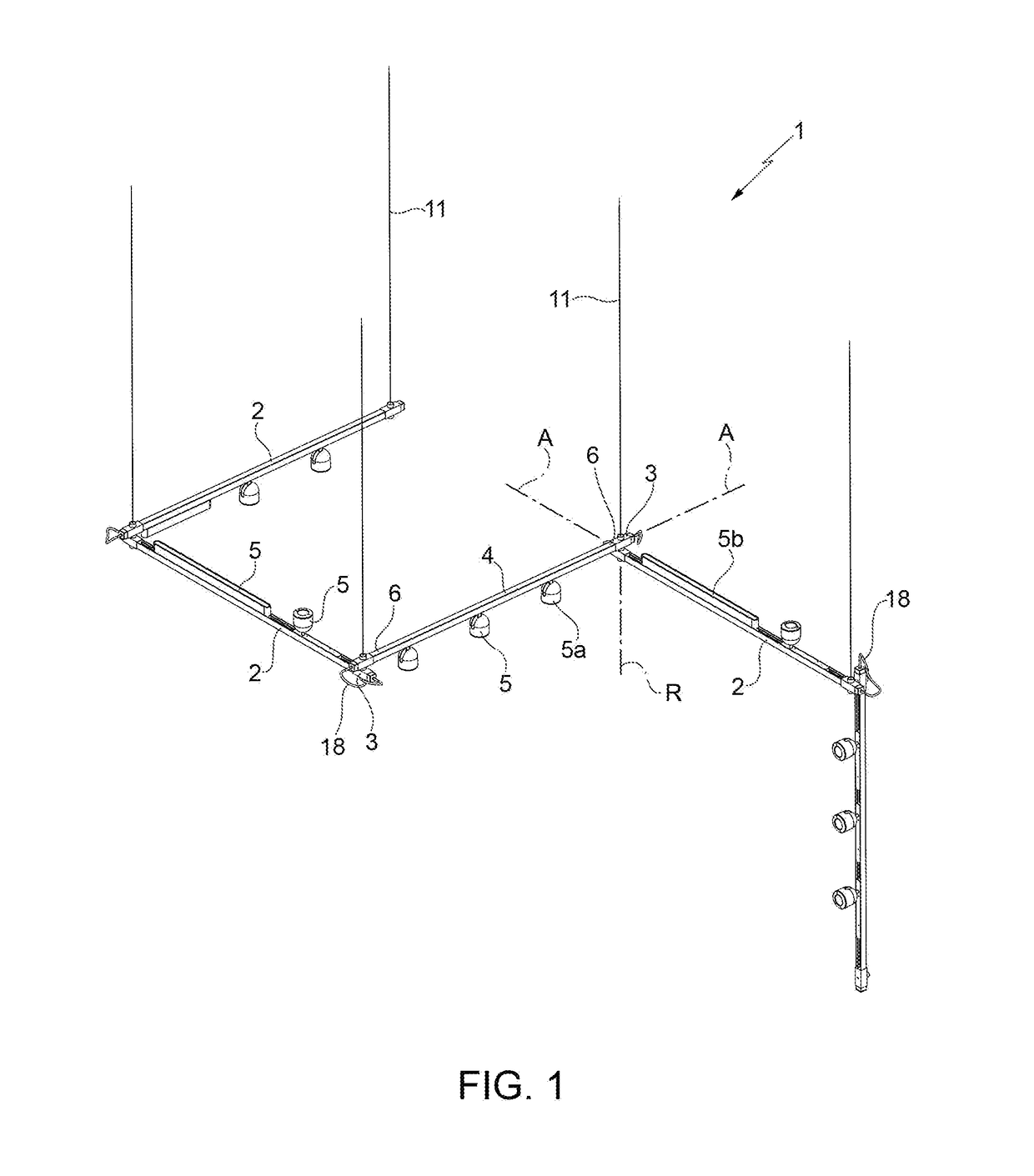
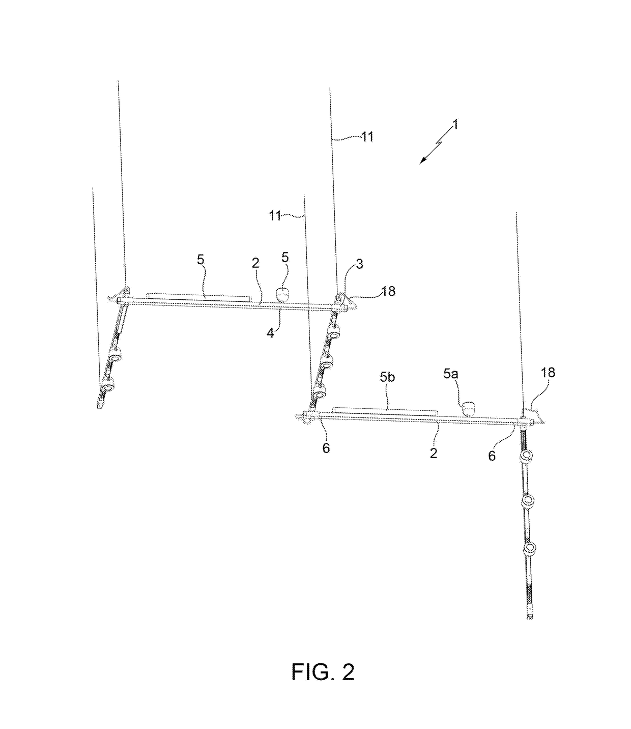
[0015]With reference to the FIGS. 1 and 2, a modular lighting system 1 comprises a plurality of combinable modules 2, joined by joints 3.

[0016]Each module 2 comprises a rail 4 elongated longitudinally along an axis A, where one or more lighting elements 5 are placed, which can be mounted reversibly onto the rail 4 by means of magnetic coupling. It is nonetheless understood that some rails 4 may also not include lighting elements 5.

[0017]The rails 4 extend along respective axes A between two opposite longitudinal ends 5 and are joined together by the joints 3.

[0018]Also with reference to FIG. 3, each joint 3 joins two rails 4 and comprises two bodies 8 joined to each other by a pin 9 that allows the two bodies to rotate in relation to each other around a rotation axis R defined by the pin 9.

[0019]The rotation axis R of a joint 3, which joins a pair of rails 4, is perpendicular to the axes A of the rails 4 joined by the joint 3.

[0020]Each body 8 has a seat 10 adapted so as to receive ...


PUM


Abstract

A modular lighting system comprises at least one module comprising a rail elongated longitudinally along an axis where one or more lighting elements are placed and mounted reversibly onto the rail by magnetic coupling, drawing power from a printed circuit board on the rail by means of spring contacts.

Description

PRIORITY CLAIM[0001]This application claims priority from Italian Utility Model Application No. 202016000037051 filed on Apr. 11, 2016, the disclosure of which is incorporated by reference,TECHNICAL FIELD[0002]The present innovation relates to a modular lighting system.BACKGROUND OF THE INVENTION[0003]Modular lighting systems consisting of lighting modules that can be variously connected to each other in different spatial configurations are known.[0004]However, in general, it seems that there is still room for improvement in the known modular lighting systems, particularly as regards their versatility, assembly and simplicity to make.[0005]For example, most of the known modular systems only allow the various modules to be assembled in one or two directions, consequently making it possible to have final configurations, which are substantially linear or two-dimensional.[0006]Furthermore, the known modular systems can, at times, present difficulties related to their assembly, also requ...

Claims


Application Information

Patent Timeline
Patent Type & Authority Applications(United States)
IPC IPC(8): F21S2/00F21V15/01F21V21/005F21S4/28
CPCF21S2/005F21V21/005F21V15/01F21S4/28F21S8/061F21S8/066F21V21/096F21V21/14F21V21/35F21Y2113/20F21Y2115/10
Inventor MOIOLI, DANIELEGALLUCCI, ANDREALEONI, PAOLO
Owner ARTEMIDE
Why Eureka
Try Eureka