
Orthopedic screw extractor

Active Publication Date: 2017-11-02
SHUKLA MEDICAL
View PDF0 Cites 4 Cited by
  • Summary
  • Abstract
  • Description
  • Claims
  • Application Information

AI Technical Summary

Benefits of technology

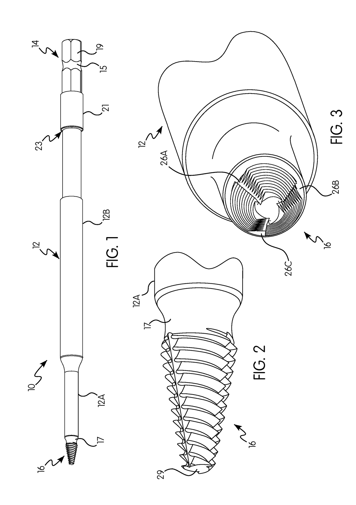
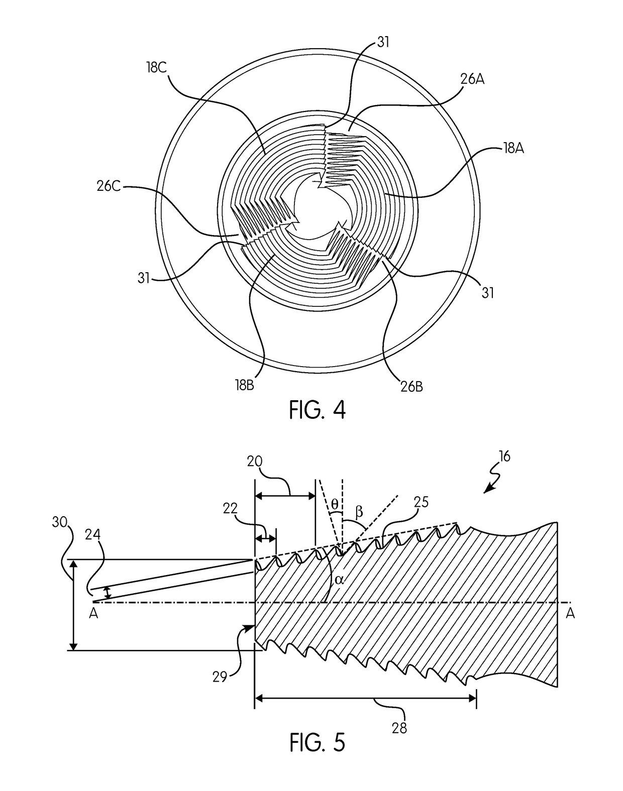
This patent describes an orthopedic screw extractor with a unique screw extracting tip that is designed to improve the removal of screws from bones. The screw extracting tip has a frustoconical shape with multiple screw threads, flutes, and, most importantly, is angled at a specific angle relative to the shaft of the extractor. This design helps to make the extractor easier to use and reduces the likelihood of complications during surgery. The technical effect of the invention is to provide an improved tool for orthopedic procedures that can safely and efficiently extract screws from bones.

Problems solved by technology

Such a procedure is particularly difficult when a screw is damaged.
For example, a head of a bone screw can be stripped, thus making it difficult to remove from bone.
Conventional orthopedic screw extractors, however, do not provide sufficient bite to lock onto and extract a stripped or damaged screw.
As a result, screw extraction is often difficult which can lead to excessive bone loss.

Method used


Image

  • Orthopedic screw extractor
  • Orthopedic screw extractor
  • Orthopedic screw extractor

Examples


Embodiment Construction

[0042]Reference will now be made in detail to the various embodiments of the present invention illustrated in the accompanying drawings. Wherever possible, the same or like reference numbers will be used throughout the drawings to refer to the same or like features. It should be noted that the drawings are in simplified form and are not drawn to precise scale. In reference to the disclosure herein, for purposes of convenience and clarity only, directional terms such as top, bottom, left, right, above, below and diagonal, are used with respect to the accompanying drawings. Such directional terms used in conjunction with the following description of the drawings should not be construed to limit the scope of the present invention in any manner not explicitly set forth.

[0043]Certain terminology is used in the following description for convenience only and is not limiting. The words “right,”“left,”“lower” and “upper” designate directions in the drawings to which reference is made. The wo...


PUM


Abstract

An orthopedic screw extractor device including a shaft, an end portion about a first end of the shaft for securing to a handle, and a screw extracting tip about a second end of the shaft opposite the first end. The screw extracting tip further includes a generally frustoconical shape having a side at an angle of about 5 to 15 degrees relative to a longitudinal axis of the screw extracting tip. The screw extracting tip further includes first, second and third screw threads and first, second and third flutes circumferentially spaced about the screw extracting tip and extending across an entire length of the screw extracting tip. Each of the screw threads has a lead of about 0.07 to 0.12 inches, a pitch of about 0.02 to 0.04 inches, a thread angle of about 40 to 50 degrees, and a depth of about 0.01 to 0.02 inches.

Description

CROSS-REFERENCE TO RELATED APPLICATIONS[0001]This application claims the benefit of U.S. Provisional Application No. 62 / 330,777, filed May 2, 2016, the entire disclosure of which is incorporated by reference herein in its entirety.BACKGROUND OF THE INVENTION[0002]The present invention relates generally to the field of orthopedic surgical instruments. In particular, the present invention relates to an orthopedic screw extractor for removing damaged orthopedic fasteners, e.g., screws.[0003]Bone screws are often used to anchor an orthopedic implant or to stabilize a bone in a patient. Occasionally, the bone screws in some patients will need to be removed or replaced by a surgeon. Such a procedure is particularly difficult when a screw is damaged. For example, a head of a bone screw can be stripped, thus making it difficult to remove from bone.[0004]Conventional orthopedic screw extractors, however, do not provide sufficient bite to lock onto and extract a stripped or damaged screw. As ...

Claims


Application Information

Patent Timeline
IPC IPC(8): A61B17/88A61B17/86
CPCA61B17/861A61B17/8888B23B51/0081B25B27/18B23B2251/66B23B51/08A61B17/8875A61B17/8877B23B2251/64A61B17/888
Inventor NAGLAPURA, SUBRAMANYALITWAK, ALFRED
Owner SHUKLA MEDICAL
Learn More