Wire connection terminal device

Active Publication Date: 2017-11-16
SWITCHLAB +1
View PDF11 Cites 3 Cited by
  • Summary
  • Abstract
  • Description
  • Claims
  • Application Information

AI Technical Summary

Benefits of technology

[0017]It is therefore a primary object of the present invention to provide a wire connection terminal device including a main body and a pressing/moving unit assembled with the main body. The pressing/moving unit has a shafted section, a cam section connected with the shafted section and a force application section formed on the cam section and a press section formed on the cam section. The cam section can freely rotate or swing within a chamber def

Problems solved by technology

This is quite inconvenient.
Also, it is more troublesome to assemble these components.
This will increase the possibility of mis-touch of the operator to the shift member 20.
This will more limit the arrangement of the environmental equipment in the working site.
However, this is unbeneficial to the structural design of the connection terminal.
This increases the

Method used


Image

  • Wire connection terminal device
  • Wire connection terminal device
  • Wire connection terminal device

Examples


Embodiment Construction

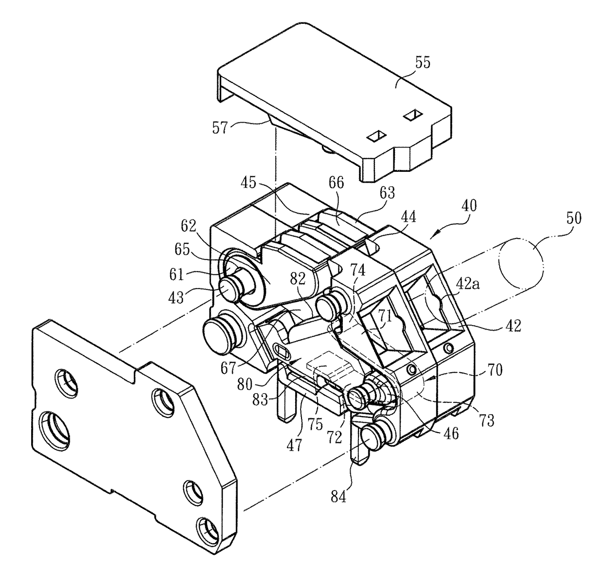
[0029]Please refer to FIGS. 4, 5 and 6. The wire connection terminal device of the present invention includes a main body 40 made of insulation material and a pressing / moving unit 60 assembled with the main body 40. The main body 40 defines a chamber 41. A metal leaf spring 70 and a terminal pin component 80 are mounted in the chamber 41. The terminal pin component 80 is plugged on a circuit board (such as a PCB, not shown). The main body 40 includes a wire inlet 42 in communication with the chamber 41 and a recessed section 42a formed on the wire inlet 42. The recessed section 42a serves to help in guiding a conductive wire 50 to plug through the wire inlet 42 into the chamber 41. After plugged into the chamber 41, the conductive wire 50 is pressed by the metal leaf spring 70 and electrically connected with the terminal pin component 80.

[0030]The upper section, upper side, lower section, lower side or bottom section mentioned hereinafter are referred to with the direction of the dr...


PUM


Abstract

A wire connection terminal device includes a main body and a pressing/moving unit assembled with the main body. The pressing/moving unit has a shafted section, a cam section connected with the shafted section and a force application section formed on the cam section and a press section formed on the cam section. The cam section can freely rotate or swing within a chamber defined by the main body. A metal leaf spring is disposed in the chamber of the main body for pressing and electrically connecting with a conductive wire. The metal leaf spring is responsive to the motion of the pressing/moving unit to release the conductive wire. The wire connection terminal device improves the shortcomings of the conventional structure that the volume of the case and the operational space are larger and the motional travel is longer.

Description

BACKGROUND OF THE INVENTION1. Field of the Invention[0001]The present invention relates generally to the structural design of a wire connection terminal device, and more particularly to a terminal device for a conductive wire to plug therein. The terminal has a pressing / moving unit. The pressing / moving unit can freely rotate or swing within a chamber of the main body of the terminal. A metal leaf spring is disposed in the chamber of the main body for pressing and electrically connecting with the conductive wire. The metal leaf spring is responsive to the motion of the pressing / moving unit to release the conductive wire from the pressing of the metal leaf spring.2. Description of the Related Art[0002]A conventional terminal device or wire-pressing terminal has an insulation case (generally made of plastic material) and a metal leaf spring mounted in the insulation case to press and electrically connect with a conductive wire plugged in the insulation case. A tool can be inserted into...

Claims


Application Information

Patent Timeline
IPC IPC(8): H01R4/48H01R9/24
CPCH01R4/4818H01R4/489H01R9/2416H01R4/48365H01R4/48185
Inventor WU, CHIH-YUANHSIAO, CHIH-KUN
Owner SWITCHLAB
Why Eureka
Try Eureka