Eureka AIR delivers breakthrough ideas for toughest innovation challenges, trusted by R&D personnel around the world.

Method for detecting lane departure and apparatus thereof

a technology of lane departure and detection method, which is applied in the field of detecting lane departure and an apparatus thereof, can solve the problems of inability to popularize related apparatuses in reality, accidents, and the like, and achieve the effects of improving the shortcomings, insufficient response time, and high error ra

Active Publication Date: 2012-11-13
AUTOMOTIVE RES & TESTING CENT
View PDF16 Cites 19 Cited by
  • Summary
  • Abstract
  • Description
  • Claims
  • Application Information

AI Technical Summary

Benefits of technology

[0008]The main objective of the present invention is to provide an improved method and apparatus for detecting lane departure, which can effectively improve the shortcomings in prior arts, such as the limited distance of usage, the insufficient response time, the inadequate comparison model, high error rate, and the false warning.
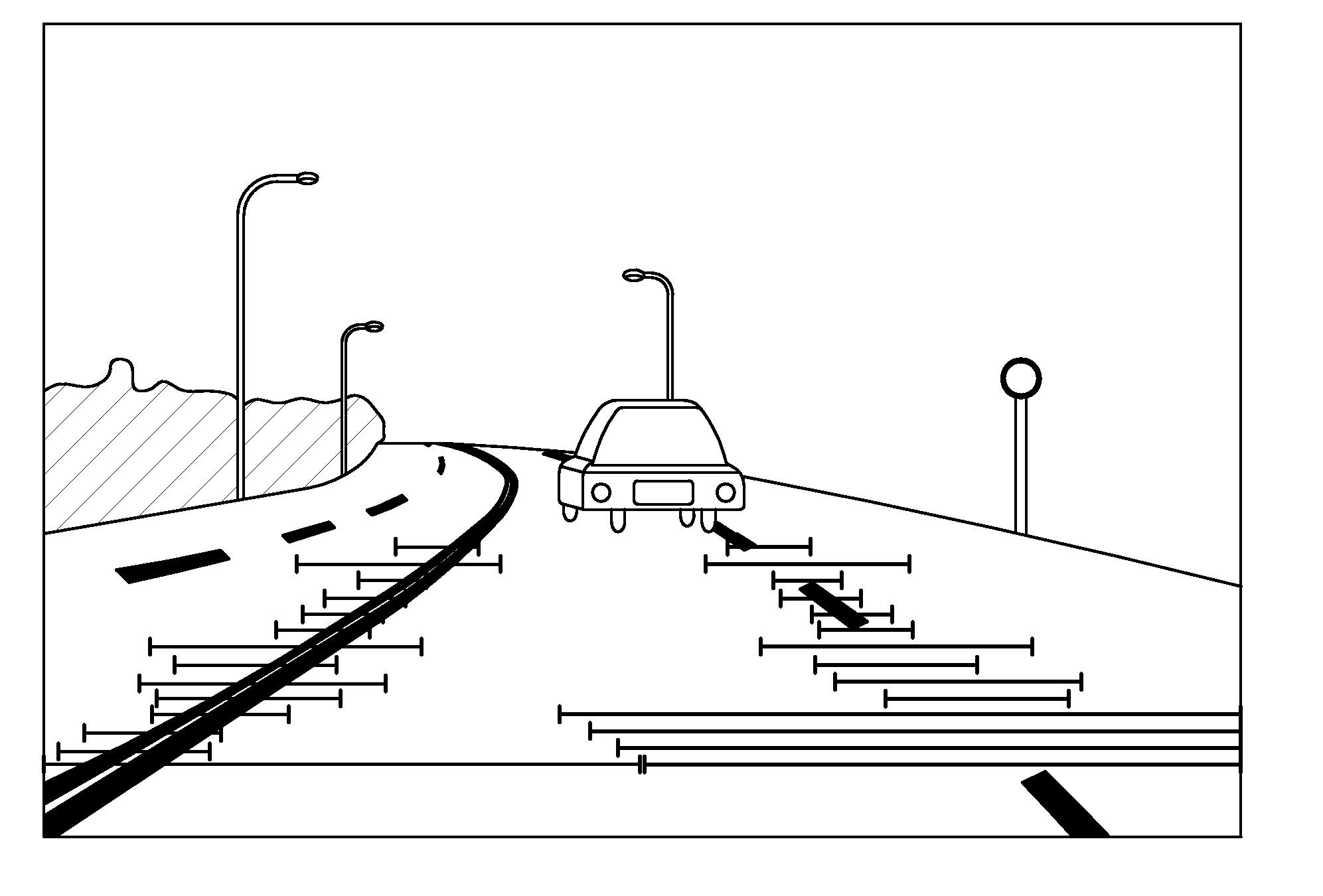
[0020]Furthermore the usage of low resolution image frame will increase the process speed efficiently. The lower half portion of the image frame data is divided into two segments. The resolution of the segment close to the vehicle is lower, but the resolution of the segment far from the vehicle is kept original resolution.

Problems solved by technology

However, such transportation improvement apparently accompanies the increment of traffic accidents.
Most of traffic accidents are induced from human driving errors, such as fatigue or inattention.
Although there are some recent researches being carried out to directly detect the driver's drowsiness via eye blinking or brain waves, the related apparatuses in reality are not easy to be popularized due to the recognition accuracy and the cost.
However, due to the prior art is only based on the comparison of the lane line markings and the traveling track of a vehicle for assuring whether the vehicle drifts away from the normal path, the track estimation process is ignored.
Thus the prior art will result in fault alarms or the error timing of alarm issuing.

Method used


Image

  • Method for detecting lane departure and apparatus thereof
  • Method for detecting lane departure and apparatus thereof
  • Method for detecting lane departure and apparatus thereof

Examples


Embodiment Construction

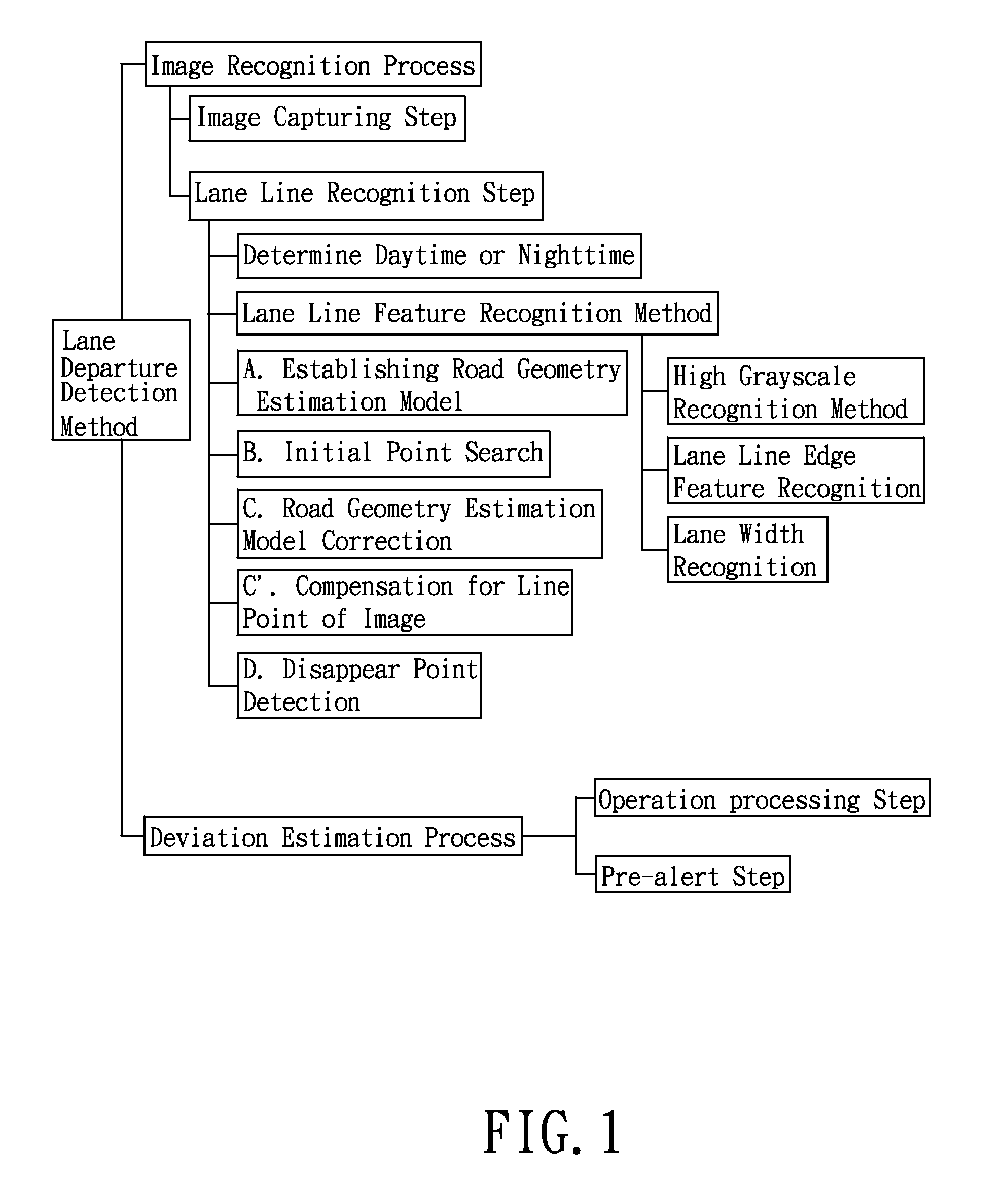
[0035]Referring to the drawings and initially to FIG. 1, a method for detecting lane departure in accordance with the present invention comprises an image recognition process and a deviation estimation process.

[0036]In the image recognition process, a quadratic curve fitting equation is used to establish a road geometry estimation model. If other vehicle shields the practical lane line, the line fitting equation can be used to solve the lane line. The line fitting equation is known in the prior art and thus the details will not be further described herein. The image recognition process has the following steps.

[0037]An image capturing step: capturing an image frame data of the road ahead of a vehicle by using an image capturing unit installed on the vehicle.

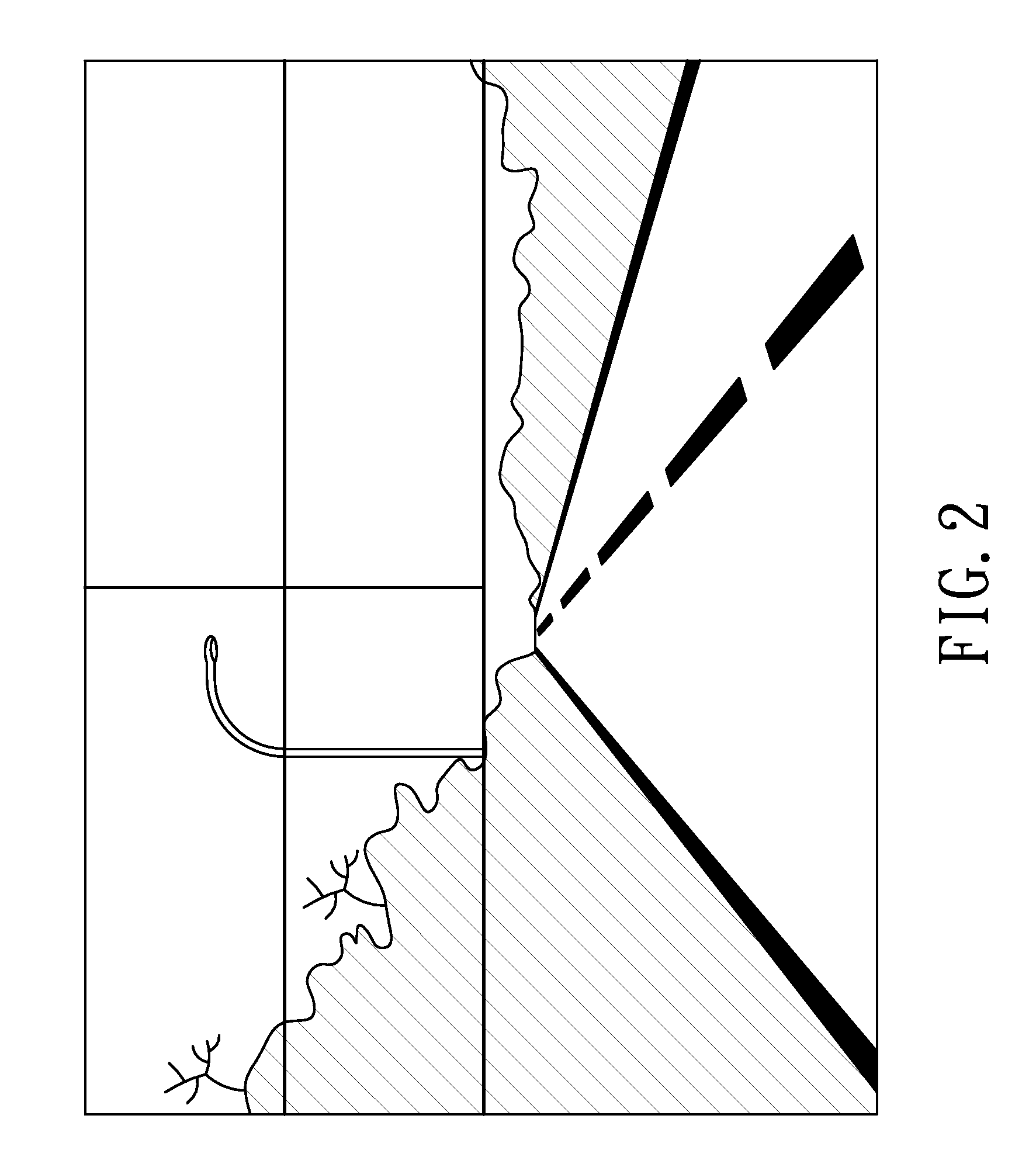
[0038]A lane line recognition step: dividing the image frame data into an upper half portion and a lower half portion. Referring to FIGS. 2 to 4, the upper half portion is divided into a plurality of sections for determining dayti...


PUM


Abstract

A method for detecting the lane departure of a vehicle includes an image recognition process and a deviation estimation process. The image recognition process includes the following steps: an image capturing step for capturing image frame data by using an image capturing unit; and a lane line recognition for analyzing the image frame data for determining the lane lines. By using a quadratic curve fitting equation, a plurality of lane line being detected so as to establish a road geometry estimation model. The road geometry estimation model is inputted into the deviation estimation process to detect the lane departure of the vehicle so as to alert the driver. Furthermore, an apparatus for detecting the deviation of the vehicle, comprising: an image capturing unit, a processing unit and a signal output unit.

Description

BACKGROUND OF THE INVENTION[0001]1. Field of the Invention[0002]The present invention relates to a method for detecting lane departure and an apparatus thereof, in that the images are used for the recognition of lane lines, and a quadratic curve fitting equation is used to derive a displacement of lane departure of a vehicle and a lane curvature so as to determine whether the vehicle travels along the normal path and thus a warning is issued.[0003]2. Description of Related Art[0004]Nowadays, with the popularity of vehicles, the geographic distance of the world is substantially shortened. However, such transportation improvement apparently accompanies the increment of traffic accidents. Therefore, more and more automotive companies worldwide have been endeavoring to develop advanced safety technologies, which can assist the driver in safer operation of the vehicle and then reduce the possibility of traffic accident occurrence.[0005]Most of traffic accidents are induced from human dri...

Claims


Application Information

Patent Timeline
Patent Type & Authority Patents(United States)
IPC IPC(8): G06K9/00
CPCB60W30/12G06K9/00798G06V20/588
Inventor WU, JUI-HUNGLIU, JING-FUSU, YI-FENG
Owner AUTOMOTIVE RES & TESTING CENT
Why Eureka
Eureka Blog
Learn More