Image coding apparatus, image coding method, storage medium, image decoding apparatus, image decoding method, and storage medium

a technology of image coding and decoding, applied in the direction of electrical apparatus, digital video signal modification, pictoral communication, etc., can solve the problems of reducing coding efficiency, insufficient use of one quantization parameter, insufficient control of both pixel value and transform coefficient, etc., and achieve the effect of increasing coding efficiency

Active Publication Date: 2017-11-16
CANON KK
View PDF11 Cites 15 Cited by
  • Summary
  • Abstract
  • Description
  • Claims
  • Application Information

AI Technical Summary

Benefits of technology

[0012]A quantization parameter may be adaptively used for each of escape coding in palette coding and non-palette coding (prediction coding). That is, compared to the case of using the same q...

Problems solved by technology

As described above, use of one quantization parameter for both escape coding and prediction coding may decrease coding efficiency.
That is,...

Method used


Image

  • Image coding apparatus, image coding method, storage medium, image decoding apparatus, image decoding method, and storage medium
  • Image coding apparatus, image coding method, storage medium, image decoding apparatus, image decoding method, and storage medium
  • Image coding apparatus, image coding method, storage medium, image decoding apparatus, image decoding method, and storage medium

Examples


first embodiment

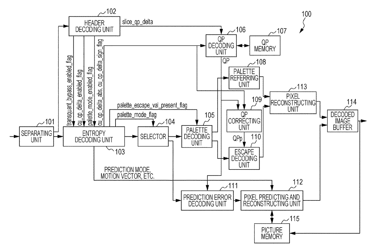
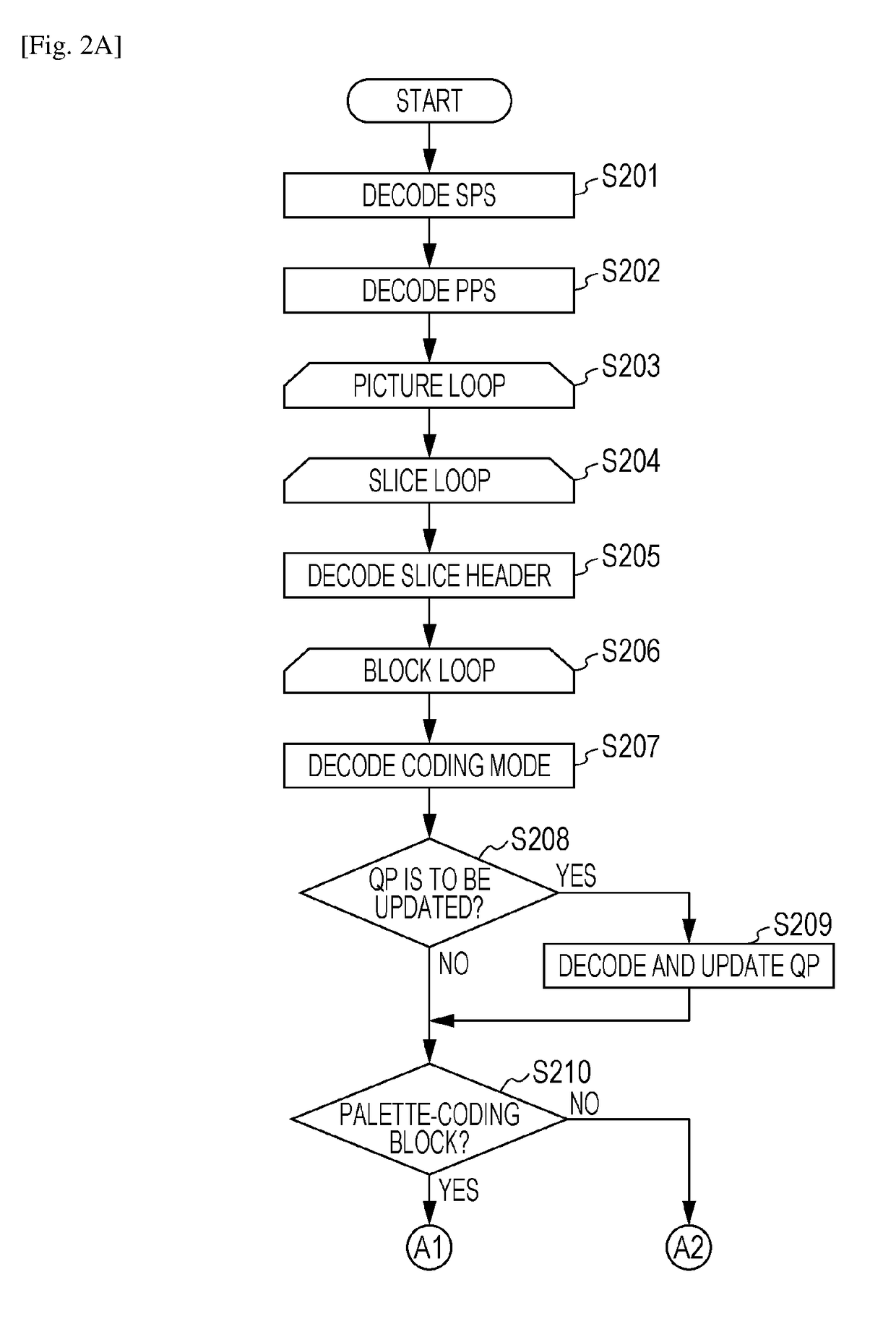
[0027]Hereinafter, an image decoding apparatus according to a first embodiment will be described with reference to the drawings. First, the configuration of an image decoding apparatus 100 according to this embodiment will be described with reference to FIG. 1. FIG. 1 is a block diagram illustrating the configuration of the image decoding apparatus 100 according to this embodiment. Referring to FIG. 1, a separating unit 101 separates, from a bit stream input to the image decoding apparatus 100, a header and a coded data. In this embodiment, the coded data constitutes pixels in units of blocks. A header decoding unit 102 decodes the header separated by the separating unit 101. Specifically, the header decoding unit 102 decodes header information, such as a sequence header, a picture header, and a slice header, and outputs them to respective units in the subsequent stage. An entropy decoding unit 103 decodes the coded data separated by the separating unit 101 and obtains information c...

second embodiment

[0087]Hereinafter, an image coding apparatus according to a second embodiment will be described with reference to the drawings. First, the configuration of an image coding apparatus 300 according to this embodiment will be described with reference to FIG. 3. FIG. 3 is a block diagram illustrating the configuration of the image coding apparatus 300 according to this embodiment. Referring to FIG. 3, a picture buffer 301 temporarily stores image data to be coded in units of pictures. A block dividing unit 302 extracts a target block to be coded from a picture input from the picture buffer 301.

[0088]A setting unit 303 determines whether or not palette coding is able to be performed on a target block to be coded, whether or not orthogonal transform and quantization are able to be omitted (skipped), and whether or not quantization parameters are able to be controlled (adjusted) in units of blocks. Here, the setting unit 303 outputs a palette_mode_enabled_flag code regarding whether or not...

third embodiment

[0140]In the above-described first embodiment, dequantization is performed by performing correction in accordance with a target of quantization. In HEVC, a quantization parameter is coded so that the quantization step becomes 1 when the value of the quantization parameter is 4. The quantization parameter is designed so that the quantization step nonlinearly increases as the value of the quantization parameter increases. In HEVC, the quantization parameter may have a value of less than 4. In this case, the quantization step becomes 1 or less, and expression with an increased number of levels of gradation is possible. This is a technique of decreasing the number of colors in palette coding. It is useless to set the quantization step to 1 or less. Accordingly, in this embodiment, a description will be given of correction processing in a case where the quantization step is 1 or less.

[0141]The configuration illustrated in FIG. 1 according to the first embodiment may be applied to the ima...


PUM


Abstract

An image decoding apparatus decodes a bit stream generated by coding an image and decodes coded data included in the bit stream and corresponding to a target block to be decoded in the image. The apparatus includes a first determining unit configured to determine whether the target block is prediction-coded or palette-coded; a second determining unit configured to determine whether or not a pixel in the target block is escape-coded if the first determining unit determines that the target block is palette-coded; and a first decoding unit configured to decode the target block by using a second quantization parameter different from a first quantization parameter if the second determining unit determines that the pixel is escape-coded. The first quantization parameter is used to decode the coded data in a case where the first determining unit determines that the target block is prediction-coded.

Description

TECHNICAL FIELD[0001]The present invention relates to techniques for coding and decoding a moving image, particularly to a palette coding technique for coding and decoding a moving image by replacing pixels with a certain limited number of colors on a palette table.BACKGROUND ART[0002]A high efficiency video coding (HEVC) scheme is available as a coding scheme for compressing and recording a moving image. As expanded specifications of HEVC, standardization of screen content coding (SCC), which enables increased compression efficiency for an artificial image different from an image captured by using a camera or the like, has been considered.[0003]A technique called palette coding has been suggested in SCC (see PTL 1). In palette coding, a predetermined number of colors are registered in a palette table. An input value of a pixel (pixel value) is compared with a color registered in the palette table, the corresponding color is indicated by an index on the palette table, and the index ...

Claims


Application Information

Patent Timeline
IPC IPC(8): H04N19/44H04N19/124H04N19/157H04N19/182
CPCH04N19/44H04N19/124H04N19/182H04N19/157H04N19/176H04N19/70H04N19/593H04N19/126H04N19/146
Inventor MAEDA, MITSURUSHIMA, MASATO
Owner CANON KK
Why Eureka
Try Eureka