Articulating surgical tool

a surgical tool and articulating technology, applied in the field of surgical instruments, can solve the problems of insufficient inconvenient use inability to properly adjust the offset of offset broach handles, etc., and achieve the effect of improving the accuracy of the offs

Inactive Publication Date: 2017-12-28
INVICTUS ORTHOPAEDICS
View PDF1 Cites 24 Cited by
  • Summary
  • Abstract
  • Description
  • Claims
  • Application Information

AI Technical Summary

Benefits of technology

[0018]A further object of the present invention is that the one or more articulating means allows articulation of the two or more sections in discrete increments.

Problems solved by technology

In minimally invasive surgery, the need to insert and operate the femoral preparation instruments through smaller incisions may conflict with the proper instrument alignment needed to create the cavity of the largest possible size.
Preparation of the femoral canal using this approach can be technically challenging.
Similarly, depending on a patient's body type, i.e., large protruding mid-section, current offset broach handles may not have adequate offset to account for such patients.
In summary, there is a current unrealized need for improved devices, systems and procedures adapted for use in minimally invasive surgery (MIS).
There is a particular unrealized need for improved devices for preparation of a patient's femur for installing a femoral component of a hip prosthesis.

Method used


Image

  • Articulating surgical tool
  • Articulating surgical tool
  • Articulating surgical tool

Examples


embodiment 1

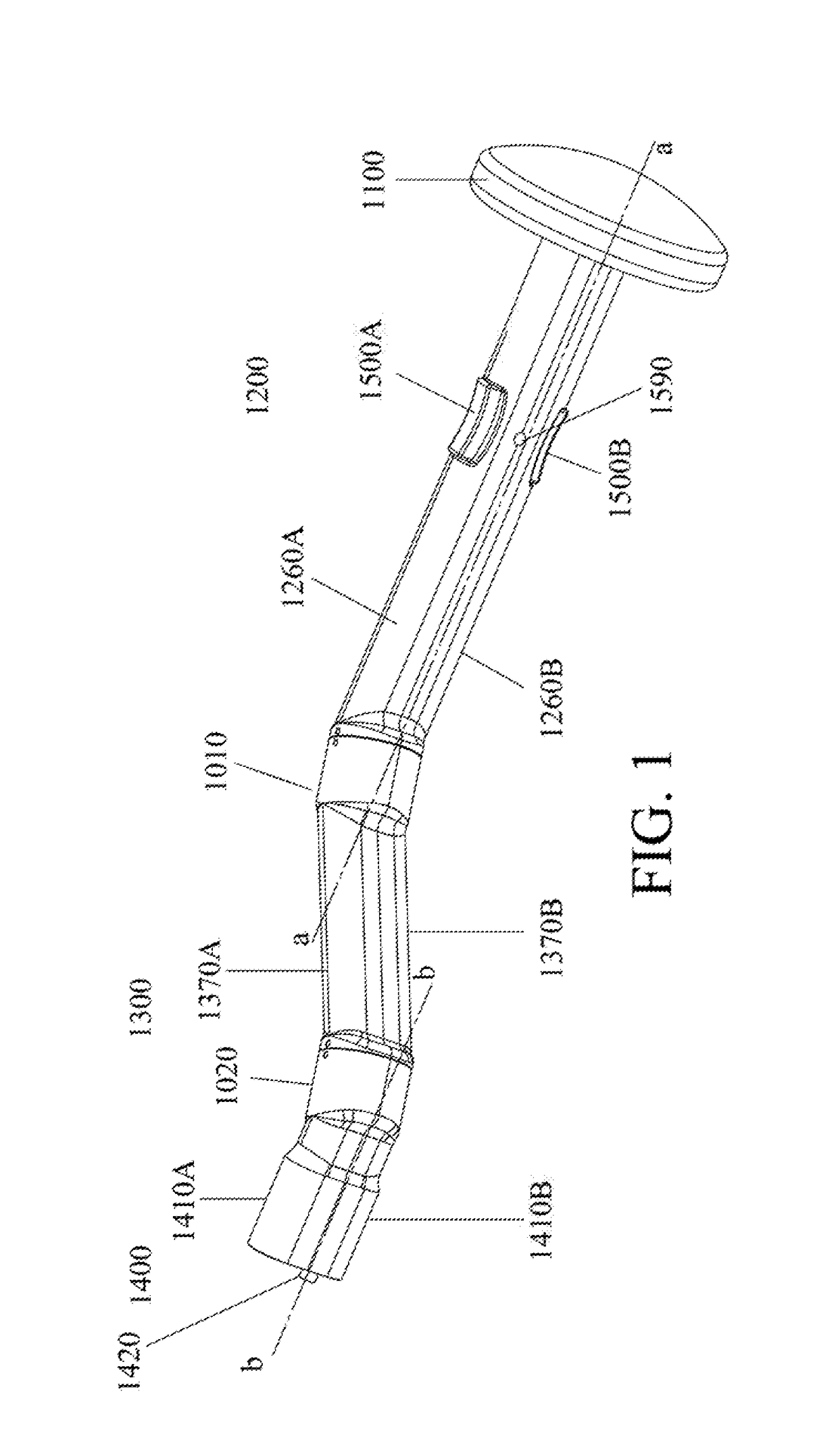
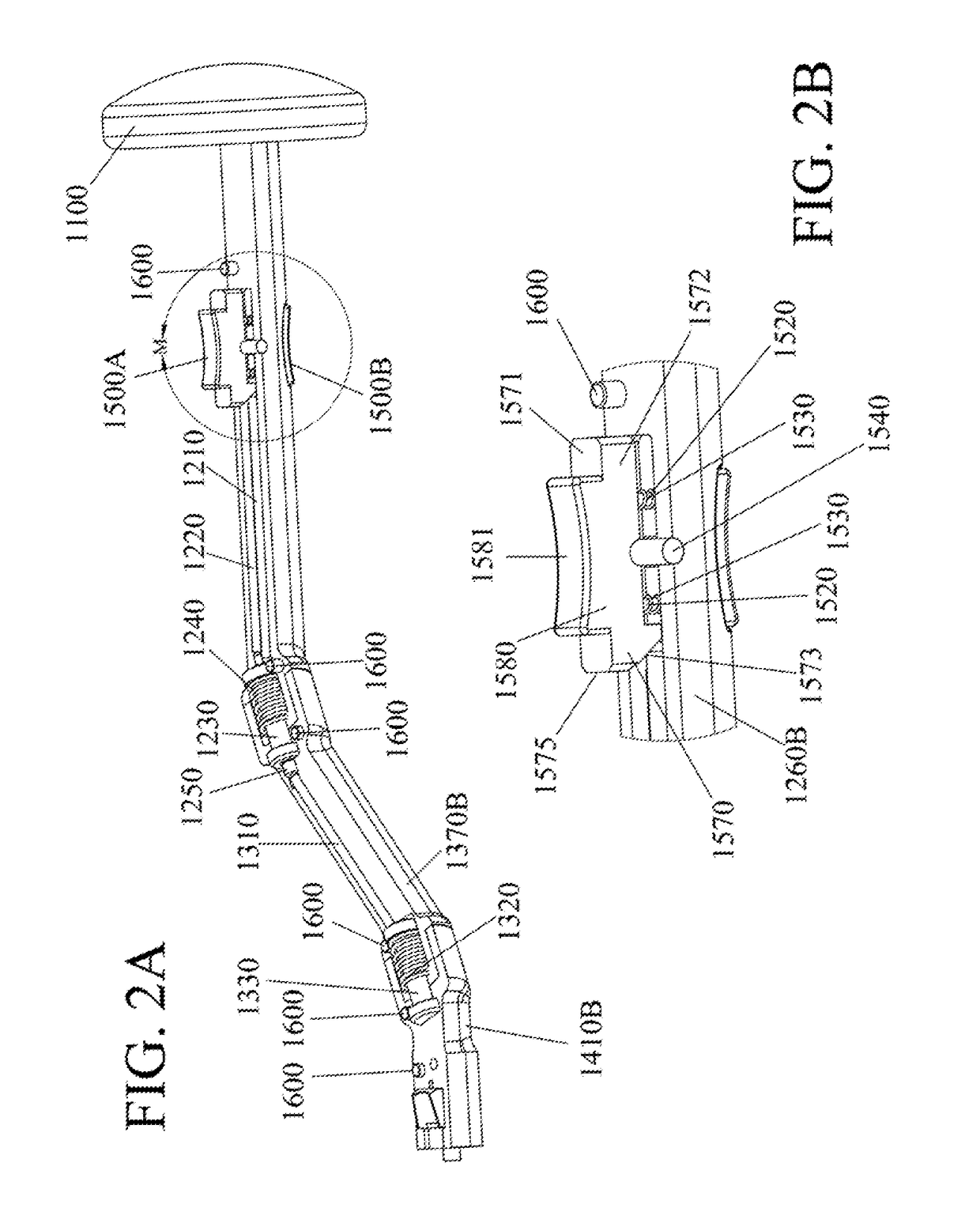
[0126]FIG. 1 depicts a first embodiment of the present invention as described in the context of a broach handle 1000. The broach handle from the proximal end to the distal end consists of a Force Disc 1100, a Main Section 1200, First and Second Triggers 1500A, 1500B, a Center Section 1300, and a Broach Section 1400. Each section (Main, Center and Broach) is constructed in two mirrored halves, top (a) and bottom (b) halves. The halves are semi-permanent or permanently affixed together. Semi-permanent attachment of the mirrored halves (sections) allow for disassembly. Each section is substantially solid with the exception of channels and cavities allowing the broach handle's internal components (described later) to be housed without excessive movement when assembled.

[0127]The proximal end of the Broach Handle 1000 comprises a circular shaped Force Disc 1100 (FIGS. 3A, 3B) and may have chamfered edges 1130. The diameter of the Force Disc is preferably 2.5 inches and a total thickness o...

embodiment 2

[0166]FIGS. 12, 13A, 13B and 14A depict a second embodiment of the articulating broach handle 2000 of this invention. Articulating broach handle 2000 includes 4 sections with 3 joints allowing articulation of the various sections. In the example described, 2 joints articulate in 45 degree increments and one joint articulates in 90 degree increments. It is understood that the amount of articulation per joint can vary. The broach handle from the proximal end to the distal end consists of a Force Disc 2100, a Main Section 2200, a First Connector Lock Sleeve 2600, a Center Section 2300, a Junction 2 2900, a Second Connector Lock Sleeve 2700, a 180 Joint 2400 (FIG. 28), a Third Connector Lock Sleeve 2800 and a Broach Section 2500. The Main and Center sections may be constructed in two mirrored halves, top (a) and bottom (b) halves or as a single structure. The halves may be semi-permanent or permanently affixed together. Semi-permanent attachment of the mirrored halves (sections) allow f...

embodiment 3

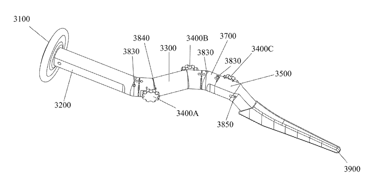
[0217]FIGS. 35 and 36A, B depict a third embodiment of the present invention as described in the context of an articulating broach handle 3000. The articulating broach handle from the proximal end to the distal end consists of a Force Disc 3100, a Main Section 3200 (FIG. 37), a Center Section 3300 (FIGS. 38A, B), a Connecting Body 3700 (FIGS. 39A, B) and a Broach Section 3500 (FIGS. 40A, B). The Main Section and the Center Section may articulate with respect to one another via a cam mechanism consisting of a Grip Cam 3400A (FIG. 41), a Push Rod 3810 (FIG. 42), a Rod Spinlock Pin 3830 (FIG. 45) and two Wheel Secure Pins 3840 (FIG. 47). A similar cam mechanism, Grip Cam 3400B, allows articulation of the Center Section 3300 with respect to the Connecting Body 3700. A third cam mechanism, Grip Cam 3400C, a Clasp Rod 3820 (FIG. 43) and two Wheel Secure Pins 3840 allows a Broach 3900 to be releasably engaged with Broach Handle 3000.

[0218]The Force Disc 3100 is similar to and provides the ...


PUM


Abstract

A surgical instrument for releasable connection to a surgical tool having two or more sections that are able to articulate 360 degrees in differing increments and directions. The articulation of the sections allows for the distal end to be spatially offset from the proximal, yet maintain parallel longitudinal axes. The surgical instrument includes a force disc at the proximal end upon which a surgeon can exert a linear force which is transmitted to the distal end having a second tool such as a broach firmly attached thereto.

Description

CROSS REFERENCE TO RELATED APPLICATIONS[0001]The present application claims the benefit of U.S. Provisional Application No. 62 / 353,261, filed on Jun. 22, 2016, and U.S. Provisional Application No. 62 / 510,111, filed on May 23, 2017, both of which are incorporated herein by reference.FIELD OF THE INVENTION[0002]The present invention generally relates to surgical instruments used in minimal incision surgery aiding in the installation of orthopedic prosthesis, and more particularly, to a surgical instrument having a releaseable connection to another surgical tool for preparing a bone site prior to the implantation of a hip prosthesis' femoral component during hip replacement surgery.BACKGROUND OF THE INVENTION[0003]Joint implants, also referred to as, for example, joint prostheses or joint replacements, are long-term surgically implantable devices that are used to partially or totally replace diseased or damaged joints, such as a hip, a knee, a shoulder, an ankle, or an elbow, within th...

Claims


Application Information

Patent Timeline
Patent Type & Authority Applications(United States)
IPC IPC(8): A61B17/16A61F2/46A61F2/32
CPCA61B17/1668A61F2/4607A61F2/32A61B17/1659A61B17/164A61B2017/0046A61F2002/30471A61F2002/30538A61B2017/922
Inventor MCCULLOCH, KENNETHD'ANTUONO, ANTHONYLANE, TROY
Owner INVICTUS ORTHOPAEDICS
Why Eureka
Try Eureka