Enhanced sanitary pad

Inactive Publication Date: 2017-12-28
ELLIS DEBORRAH R PEOPLES
33 Cites 5 Cited by

AI-Extracted Technical Summary

Problems solved by technology

However, many women do not like to use the vaginal inserts because of various issues.
Amongst these are discomfort, hygiene issues, religious reasons, as well as the fact that it has been shown that these devices can have toxic effects because of the various chemicals embedded therein.
However, one problem with this system that has not been addressed is that users sometimes experience rashes or fail to recognize when the pad has become full.
Another issue with most modern sanitary pads is that they have no way of ensuring a correct fit because of the limitations of their manufacture.
Other problems of form, fit and finis...

Method used

[0064]The pads taught herein are formable in various shapes so as to improve the fit and liquid absorption. Tape and or wings are also additional options that are combinable with any of the embodiments taught herein. These pads have increased absorbability, leak prevention, enhanced comfort and obscurity. Additionally, the pads have a cooling option to alert a user when the pad is almost full.
[0076]FIG. 4 presents a raised protrusion 5 having a cooling strip 8 thereon for use in ...

Abstract

An Enhanced Sanitary Pad has various optional devices associated therewith in order to ameliorate painful conditions and also signal the amount of liquids absorbed therein. In this regard, cooling crystals are embedded within an absorbent layer attached to a plastic backing material. Another option has a cooling strip associated with the pad at either end thereof, on the longitudinal sides of the pad, at a side of an optional raised protrusion located on the pad or on the raised protrusion itself. This protrusion is also formed of tightly wound absorbent material and is either stitched or supported with adhesive interlay to maintain its shape; it is optionally removable from the pad and associated therewith using corresponding velcro interlocks.

Application Domain

Sanitary towelsBandages

Technology Topic

Biomedical engineeringCrystal +1

Image

  • Enhanced sanitary pad
  • Enhanced sanitary pad
  • Enhanced sanitary pad

Examples

  • Experimental program(1)

Example

[0061]Like reference numerals refer to like parts throughout the several views of the drawings.
DETAILED DESCRIPTION
[0062]The following detailed description is merely exemplary in nature and is not intended to limit the described embodiments or the application and uses of the described embodiments. As used herein, the word “exemplary” or “illustrative” means “serving as an example, instance, or illustration.” Any implementation described herein as “exemplary” or “illustrative” is not necessarily to be construed as preferred or advantageous over other implementations. All of the implementations described below are exemplary implementations provided to enable persons skilled in the art to make or use the embodiments of the disclosure and are not intended to limit the scope of the disclosure, which is defined by the claims. For purposes of description herein, the terms “upper”, “lower”, “left”, “rear”, “right”, “front”, “vertical”, “horizontal”, and derivatives thereof shall relate to the invention as oriented in each figure.
[0063]Furthermore, there is no intention to be bound by any expressed or implied theory presented in the preceding technical field, background, brief summary or the following detailed description. It is also to be understood that the specific devices and processes illustrated in the attached drawings, and described in the following specification, are simply exemplary embodiments of the inventive concepts defined in the appended claims. Hence, specific dimensions and other physical characteristics relating to the embodiments disclosed herein are not to be considered as limiting, unless the claims expressly state otherwise.
[0064]The pads taught herein are formable in various shapes so as to improve the fit and liquid absorption. Tape and or wings are also additional options that are combinable with any of the embodiments taught herein. These pads have increased absorbability, leak prevention, enhanced comfort and obscurity. Additionally, the pads have a cooling option to alert a user when the pad is almost full.
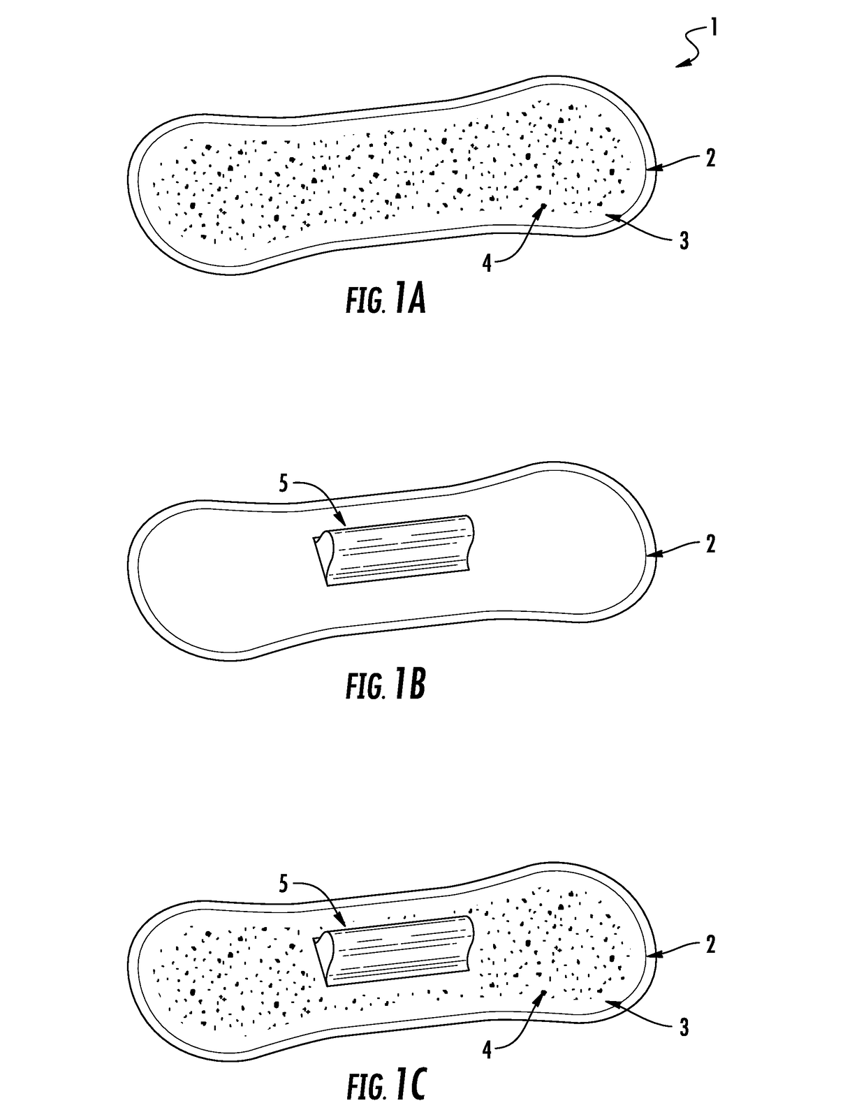
[0065]FIG. 1A presents an Enhanced Sanitary Pad having cooling crystals embedded within the absorbent material in an embodiment disclosed herein. An Enhanced Sanitary Pad 1 has a rim 2 that represents two different types of pads; first, it represents a turned over edge for a single plastic backing pad that grips an absorbent material layer using adhesives, heat treatment, glues and or similar modalities; or secondly, it represents a peripheral edge of a two plastic layered sanitary pad where the two plastic layers are attached together through adhesives, heat treatment, glues and or similar modalities such that they together grip the absorbent material layer there between.
[0066]A layer of absorbent material 3 including cellulose and polymer is attached to the single plastic layer or between the two layers of plastic. Cooling crystals 4 are mixed into the absorbent material whether combined as cellulose and polymer or within only one or the other or within similar materials sandwiched within the plastic layer(s) or attached thereto using adhesives, heat treatment glues and or similar modalities.
[0067]FIG. 1B presents an Enhanced Sanitary Pad having a raised protrusion in an embodiment disclosed herein. A raised protrusion 5 is integrally formed of absorbent material packed together in a tightly formed shape and attached together through adhesives, glue, heat treatment, staples but is preferably made from simply packing the device tightly and inserting the loose end within a suitable opening in the protrusion 5. This raised protrusion 5 is shown at the center of the pad and is formed integrally with the absorbent material 3 so that the raised protrusion can be placed up against the vaginal opening but not within it. The protrusion 5 is meant to capture the menstrual fluids and other liquids that are expelled from the feminine parts and to provide a snug fit thereby avoiding dripping down the inner sides of the users legs.
[0068]FIG. 1C presents an Enhanced Sanitary Pad having a raised protrusion 5 and cooling crystals 4 embedded within the absorbent material 3 in an embodiment disclosed herein.
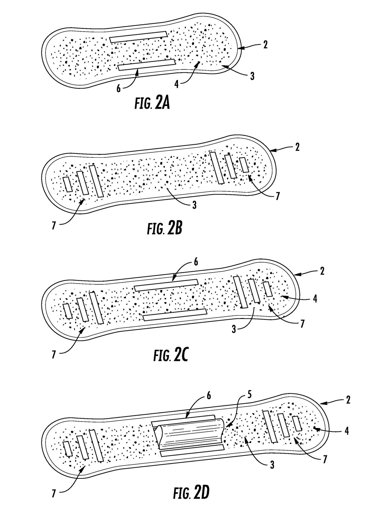
[0069]FIG. 2A presents an Enhanced Sanitary Pad having cooling crystals 4 and longitudinal cooling strips 6 in an embodiment disclosed herein. The cooling strips 6 are plastic strips attached to the top surface of the absorbent material 3 that are located midway between the length of the pad and near the top and bottom edge thereof as shown in the figure. The cooling strips 6 have any of the Cooling Gel substances spread thereon such as methyl salicylate topical.
[0070]FIG. 2B presents an Enhanced Sanitary Pad having cooling crystals 4 in absorbent material 3 and transverse cooling strips 7 at opposite narrow ends of the pad in an embodiment disclosed herein. The cooling strips 7 decline in size as they approach each opposite end thereof. However, it should be understood that this is only an optional design size for cosmetic reasons and that the sizes do not need to decline but are alternatively the same size or decline inwardly towards the center of the pad. These strips 7 are made from plastic and are similarly attached to the absorbent material layer 3 as were strips 6.
[0071]FIG. 2C presents an Enhanced Sanitary Pad having cooling crystals 4 and transverse cooling strips 7 at opposite narrow ends of the pad as well as longitudinal cooling strips 6 in an embodiment disclosed herein.
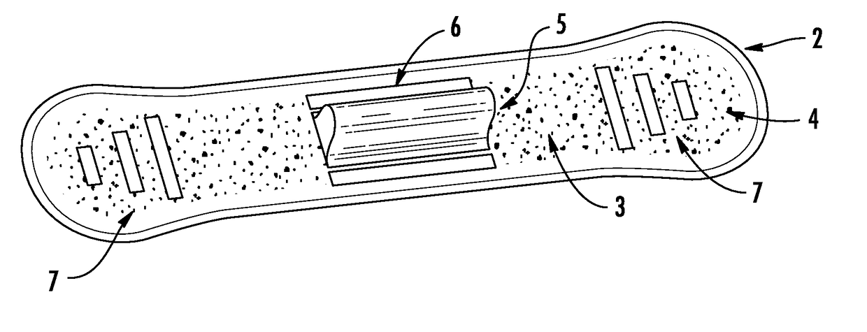
[0072]FIG. 2D presents an Enhanced Sanitary Pad having cooling crystals 4 and transverse cooling strips 7 at opposite narrow ends of the pad as well as longitudinal cooling strips 6 and a raised protrusion 5 in an embodiment disclosed herein. Absorbent material 3 has various cooling crystal 4 embedded therein. The longitudinal cooling strips 6 are presented as being on either side of the raised protrusion 6 and attached to the top surface of the pad.
[0073]FIG. 2E presents an Enhanced Sanitary Pad having cooling crystals 4 as well as longitudinal cooling strips 7 disposed on opposite sides of a raised protrusion 5 in an embodiment disclosed herein. Here they are disclosed at top and bottom sides of the raised protrusion 5 or near the outer opposite longitudinal edges of the pad.
[0074]FIG. 2F presents an Enhanced Sanitary Pad having cooling crystals 4 embedded in absorbent material 3 as well as transverse cooling strips 7 disposed on opposite ends of the pad 1 as well as having a raised protrusion 5 in an embodiment disclosed herein. The raised protrusion is shown being midway from either narrow end of the pad.
[0075]FIG. 3 presents a plastic strip 6, 7, 8 integral with an Enhanced Sanitary pad having a cooling gel 6B, 7B , 8B thereon covered by a removable plastic strip 6A, 7A ,8A used in an Enhanced Sanitary Pad in an embodiment disclosed herein; the dotted line represents the edge of the pad. The cooling strip 6, 7, 8 are shown in other figures herein disposed at various locations. It should be understood that this strip is alternatively attached (adhesive, glue, heat treatment, integrally formed therefrom) to the absorbent material layer 3, or directly to the underlying plastic forming the primary backing layer through a hole (not shown) in the absorbent material layer 3. A cooling gel 6B, 7B , 8B is applied during manufacture and assembly to the surface of the cooling strip 6, 7, 8. Finally, in order for the cooling gel to be available to a user when needed, an optional cover is applied thereto in the form of a removable plastic strip 6A, 7A ,8A having either surface tension adhesion with the gel or a weak adhesive suitable for this purpose.
[0076]FIG. 4 presents a raised protrusion 5 having a cooling strip 8 thereon for use in an Enhanced Sanitary Pad in an embodiment disclosed herein. The cooling strip 8 is disposed upon a longitudinal side of the protrusion 5 through the use of glues adhesive or heat treatment; of course, it could just as easily be disposed on a transverse side. Additionally, the shape of the protrusion 5 is in any convenient shape so desired. Examples of these shapes include a wedge, a plug, a mushroom, a nipple, rectangular, pyramidal, triangular, circular, elliptical and so forth.
[0077]FIG. 5 presents a removable raised protrusion 5 useable in an Enhanced Sanitary Pad in an embodiment disclosed herein. The protrusion 5 is essentially a construct of absorbent material that is formed from one or more pieces of absorbent material; these are brought together then woven together, stitched together, adhesively connected, glued, heat treated or chemically treated to maintain an appropriate physical size. An alternative manufacturing option would be to have the material wound about a supporting jig in association with a rotating dispensing spool.
[0078]The supporting jig is centrally disposed and rotates on its axis while the spool similarly rotates on its axis thereby forming the protrusion; alternatively, the jig is stationary and the spool of material rotates on its axis and also revolves about the supporting jig using an armature for this purpose. The various motions described are provided by electric motors disposed thereabout. In either scenario, the material is then cut and the end thereof is attached to the rest of the absorbent material forming the protrusion by physical insertion of its end into a opening in the absorbent material and wrapping it together or through the use of glue, adhesives, heat treatment or chemical bonding agents.
[0079]A strip 9 of velcro material is applied to the bottom of the protrusion 5 for selective engagement with a corresponding piece of velcro strip similarly attached to a top portion of absorbent material of the pad. Alternatively, the corresponding piece of velcro material is attached to an outer first or second top or bottom layer of plastic backing material forming the pad. A flap (not shown) of absorbent material (or plastic backing material) formed from the absorbent material (or plastic backing material) integrally attached to the pad and plastic backing layers also has an optional velcro material strip attached thereto. This flap strip of velcro attaches to the first one integral with the pad so as to ensure that when the protrusion is removed a user can still use the pad without discomfort turning the flap over onto the integrally formed velcro material attached to a top portion of absorbent material or onto an outer first or second top or bottom layer of plastic backing material.
[0080]Another option instead of velcro is to have a double sided strip of material 9 permanently attached on one side thereof using strong adhesives or glues to the bottom of the protrusion 5. The other side of the strip of material 9 has another adhesive, glue or sticky gel on its underside that is to attach to a user clothing. Thus, a user can place this underside in the undergarment and attach it thereto so as to maintain its position on the undergarment using appropriately strong adhesives, glues, sticky gels or similar modalities. Thus, a user can remove the protrusion 5 from the pad and use it separately from the pad as desired or it can be bought separately at a store. Another option has a removable plastic strip attaching to this other side of the strip of material 9 for protection of the attachment modality, namely, glues, adhesive or sticky gels.
[0081]It should be apparent that in the event the protrusion is not removable then it either its underside is attached using heat treatment, glues, adhesives or chemical additives to the absorbent material formed on the plastic backing layers.
[0082]The above-described embodiments are merely exemplary illustrations of implementations set forth for a clear understanding of the principles of the invention. Many variations, combinations, modifications or equivalents may be substituted for elements thereof without departing from the scope of the invention. Therefore, it is intended that the invention not be limited to the particular embodiments disclosed as the best mode contemplated for carrying out this invention, but that the invention will include all the embodiments falling within the scope of the appended claims.

PUM

no PUM

Description & Claims & Application Information

We can also present the details of the Description, Claims and Application information to help users get a comprehensive understanding of the technical details of the patent, such as background art, summary of invention, brief description of drawings, description of embodiments, and other original content. On the other hand, users can also determine the specific scope of protection of the technology through the list of claims; as well as understand the changes in the life cycle of the technology with the presentation of the patent timeline. Login to view more.
Why Eureka
Try Eureka