
Power supply for providing electrical energy to a self-destruct fuze for submunitions contained in a projectile

Inactive Publication Date: 2018-02-22
OMNITEK PARTNERS LLC
View PDF0 Cites 0 Cited by
  • Summary
  • Abstract
  • Description
  • Claims
  • Application Information

AI Technical Summary

Benefits of technology

The patent describes a method for developing power sources for submunitions with self-destruct fuzes that have no power until the projectile is fired. This ensures safe handling and storage of the submunitions during production and assembly. The safety features can be integrated into the design of the power source. The patent also provides several embodiments of power sources with integrated safety mechanisms.

Problems solved by technology

However, foot soldiers may be spread out over a large area and the damage caused by a conventional shell is too localized to be effective in such scenarios.
The use of improved conventional munitions (ICMs) which can deliver a very large number of submunitions by means of an artillery or rocket carrier on a target area has increased the problem of hazardous duds that remain on the battlefield.
The danger to follow-up friendly personnel has increased in recent time because of the large quantities of ICM carriers that have been deployed in each mission.
Because of the large quantity of submunitions now deployed during each mission, all prior inputs have proven to still leave a prohibitive number of hazardous duds on the battlefield.
The minimization of dangerous duds is very important since if they are scattered over the battlefield, they would pose hazard to friendly troops and even to civilians or wildlife long after the battle.
However, once the firing pin is moved to the armed position however, an impact or similar jolt will cause the pin to detonate the detonator, igniting the warhead and thereby causing the submunition grenade to explode.
Like all mechanical systems, such slider assemblies are not fail-safe.
One disadvantage of the prior art submunition fuzes described above, is that where the submunition grenade impacts with an inappropriate surface, such as a soft surface, or where the angle of impact is wrong, such that the firing pin is not induced to strike the detonator, the grenade is not detonated.
Consequently, there is a risk of armed submunition grenades launched at the enemy but not detonated on impact being left scattered over the battlefield.
Armed dud submunition grenades remain dangerous, and pose a risk to friendly troops and even to civilians long after the battle.
In certain scenarios, the submunitions may be accidentally ejected from the assembled round due to nearby explosions, fire or other similar events.
Following such accidents, the submunitions is usually armed, posing a very serious safety problem.
), there is still a risk of armed submunition grenades being dispersed over the battlefield but not detonated.

Method used


Image

  • Power supply for providing electrical energy to a self-destruct fuze for submunitions contained in a projectile
  • Power supply for providing electrical energy to a self-destruct fuze for submunitions contained in a projectile
  • Power supply for providing electrical energy to a self-destruct fuze for submunitions contained in a projectile

Examples


Embodiment Construction

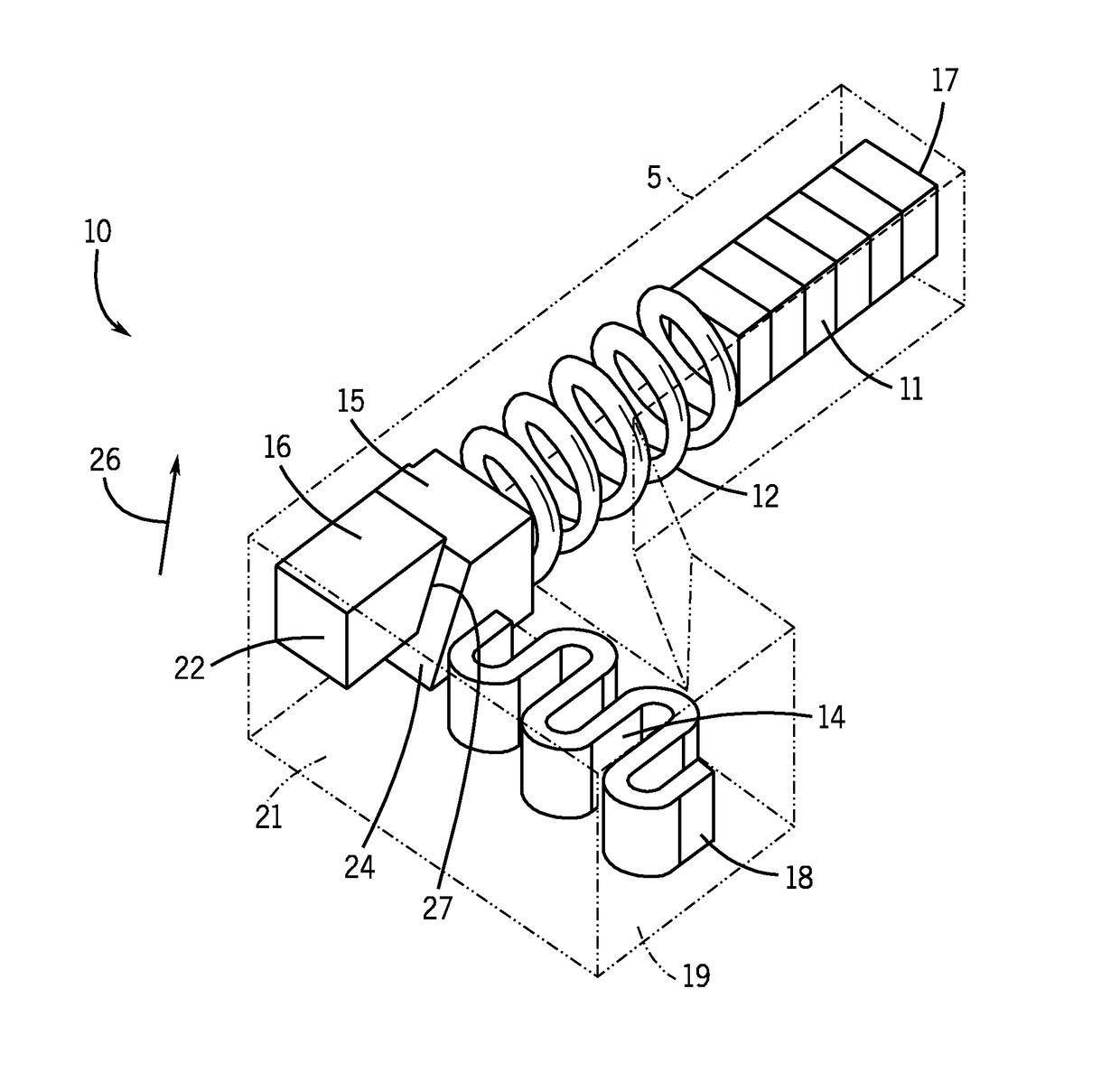
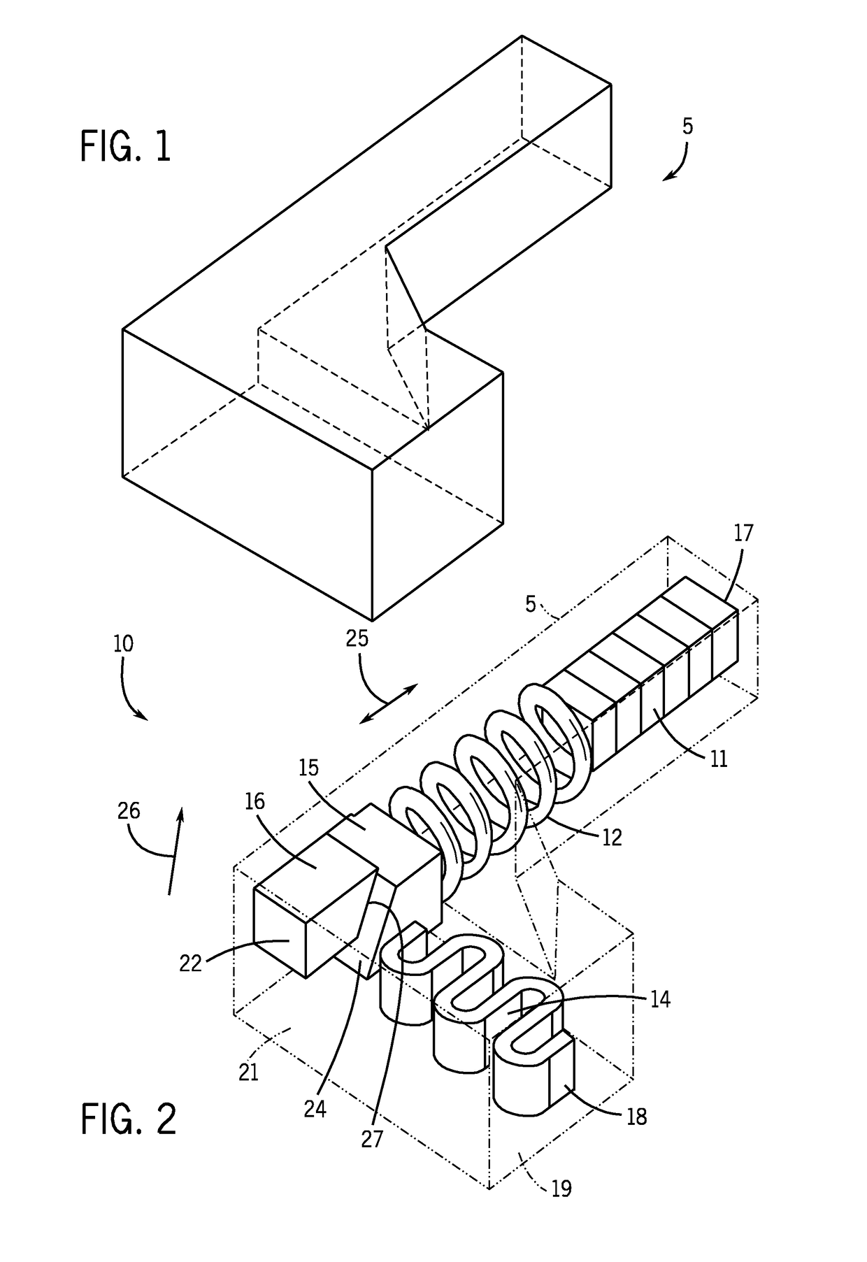
[0040]In general, the amount of space available for power sources and for the aforementioned safety mechanisms in submunitions self-destruct fuze is very small, making the use of chemical reserve batteries very difficult and costly, and nearly impractical. The use of active chemical batteries is not possible in submunitions due to the up to 20 years of shelf life requirement and also due to safety concerns that an active battery would generate. A typical volume available for a power source and its safety mechanisms is shown in FIG. 1 together with typical dimensions of this available space (see for example U.S. Pat. No. 5,387,257 by M. Tari, et al.). As can be observed, the available volume is very small and in many cases is a complex shape.

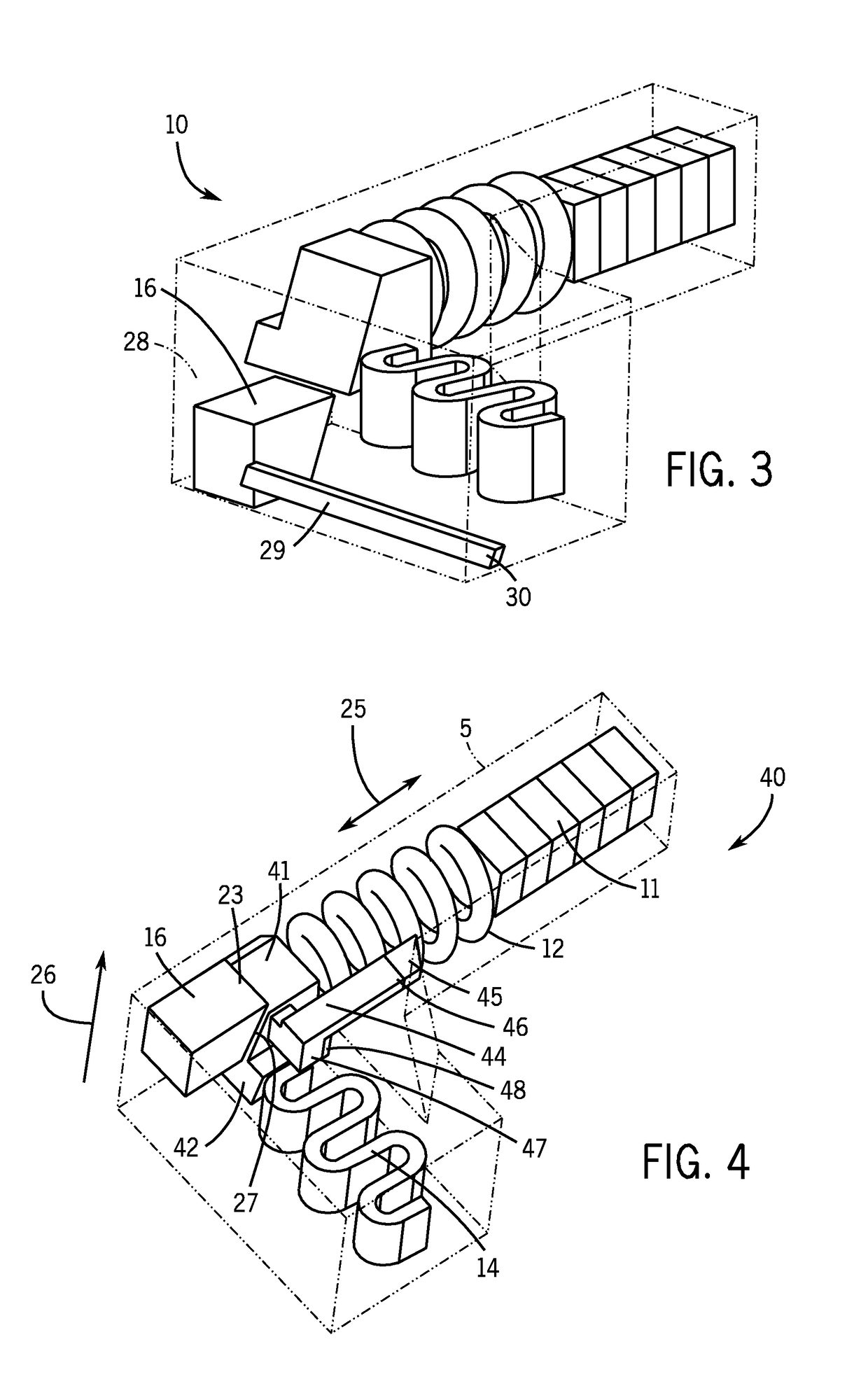
[0041]A method and apparatus are provided for power sources that could be designed to fit inside the available volume of the geometrical shape shown in FIG. 1 or other similarly complex shapes. In one embodiment, the power sources have substantia...


PUM


Abstract

A device for providing electrical energy in a submunition of a projectile upon an expulsion acceleration of the submunition from the projectile, the device including: at least one elastic element and a mass connected to the at least one elastic element such that a firing acceleration of the projectile deforms to store mechanical energy in the elastic element; and a mechanism for locking the elastic element in the deformed position and unlocking the elastic element due to the expulsion acceleration to vibrate the at least one elastic element and mass and apply a cyclic force to at least one piezoelectric element to convert the stored mechanical energy to electrical energy.

Description

CROSS -REFERENCE TO RELATED APPLICATIONS[0001]This application is a Continuation Application of U.S. patent application Ser. No. 15 / 152,491, filed on May 11, 2016, issuing as U.S. Pat. No. 9,791,252, which is a Divisional of U.S. patent application Ser. No. 13 / 631,974 filed on Sep. 20, 2012, issuing as U.S. Pat. No. 9,341,458, which is a Divisional Application of U.S. application Ser. No. 12 / 481,550 filed on Jun. 9, 2009, issuing as U.S. Pat. No. 8,281,719, which claims benefit to earlier filed provisional application serial number 61 / 131,430 filed on Jun. 9, 2008, the entire contents of each of which are incorporated herein by reference.GOVERNMENT RIGHTS[0002]This invention was made with Government support under Agreement No. DAEE30-03-C-1077 awarded by the Department of Defense. The Government has certain rights in the invention.FIELD[0003]The present invention relates generally to power source and safety mechanisms for munitions, particularly an electrically operated self-destruc...

Claims


Application Information

Patent Timeline
IPC IPC(8): F42C11/02F42C15/44F42C11/00F42C9/16
CPCF42C15/44F42C11/008F42C9/16F42C11/02
Inventor RASTEGAR, JAHANGIR S.MURRAY, RICHARD T.JANOW, CHRISDRATLER, RICHARD
Owner OMNITEK PARTNERS LLC
Learn More