Garbage remover helper

Active Publication Date: 2018-03-08
JOHNSON LETRICIA DIAHNE
View PDF0 Cites 1 Cited by
  • Summary
  • Abstract
  • Description
  • Claims
  • Application Information

AI Technical Summary

Benefits of technology

[0004]To accomplish this, the garbage bin device comprises a bottom section having a front side spaced apart from a back side, a left side spaced apart from a right side, a top side spaced apart from a bottom side, and a pair of spaced apart rounded corners. Each of the pair of rounded corners is disposed proximal each of the front side and the bottom side. The rounded corners specifically enable a user to easily tilt the garbage bin device forward as desired. A pair of spaced apart wheel recesses is also provided. A first wheel recess is disposed proximal each of the bottom side, the back side, and the right side, and a second wheel recess is disposed proximal each of the bottom side, the back side, and the left side. A wheel is disposed in each wheel recess. Recessing the wheels allows for the garbage bin device to be transported without the wheels catching on various objects and doorways, a problem that commonly occurs during the transport of most garbage bins on the market today. Furthermore, each wheel protrudes beyond the back side so that the garbage bin device can be easily tilted backwards and forwards.
[0005]A pivoting handle is disposed on each of the left side and the right side. Each pivoting handle is disposed more proximal the top side than the bottom side. Such positioning of the handles allows a user to more easily balance the garbage bin device as needed, especially when loaded. A bottom opening is disposed in the bottom side and provides a bottom side access that is not available in other garbage bins. An L-shaped channel is disposed around the bottom opening and is extended upwardly within the back side. A rounded section is disposed within the L-shaped channel between the back side and the bottom side. An accordion door is slidably disposed within the L-shaped channel. A handle slot is disposed vertically within the back side proximal the bottom side and upwardly therefrom. A t-handle pivotally connects within the handle slot to the accordion door. The t-handle is disposed within the back side. A pair of handle hooks is disposed above the handle slot. The pair of handle hooks is in selective r

Problems solved by technology

Recessing the wheels allows for the garbage bin device to be transported without the wheels catching on various o

Method used


Image

  • Garbage remover helper
  • Garbage remover helper
  • Garbage remover helper

Examples


Example

DETAILED DESCRIPTION OF THE DRAWINGS

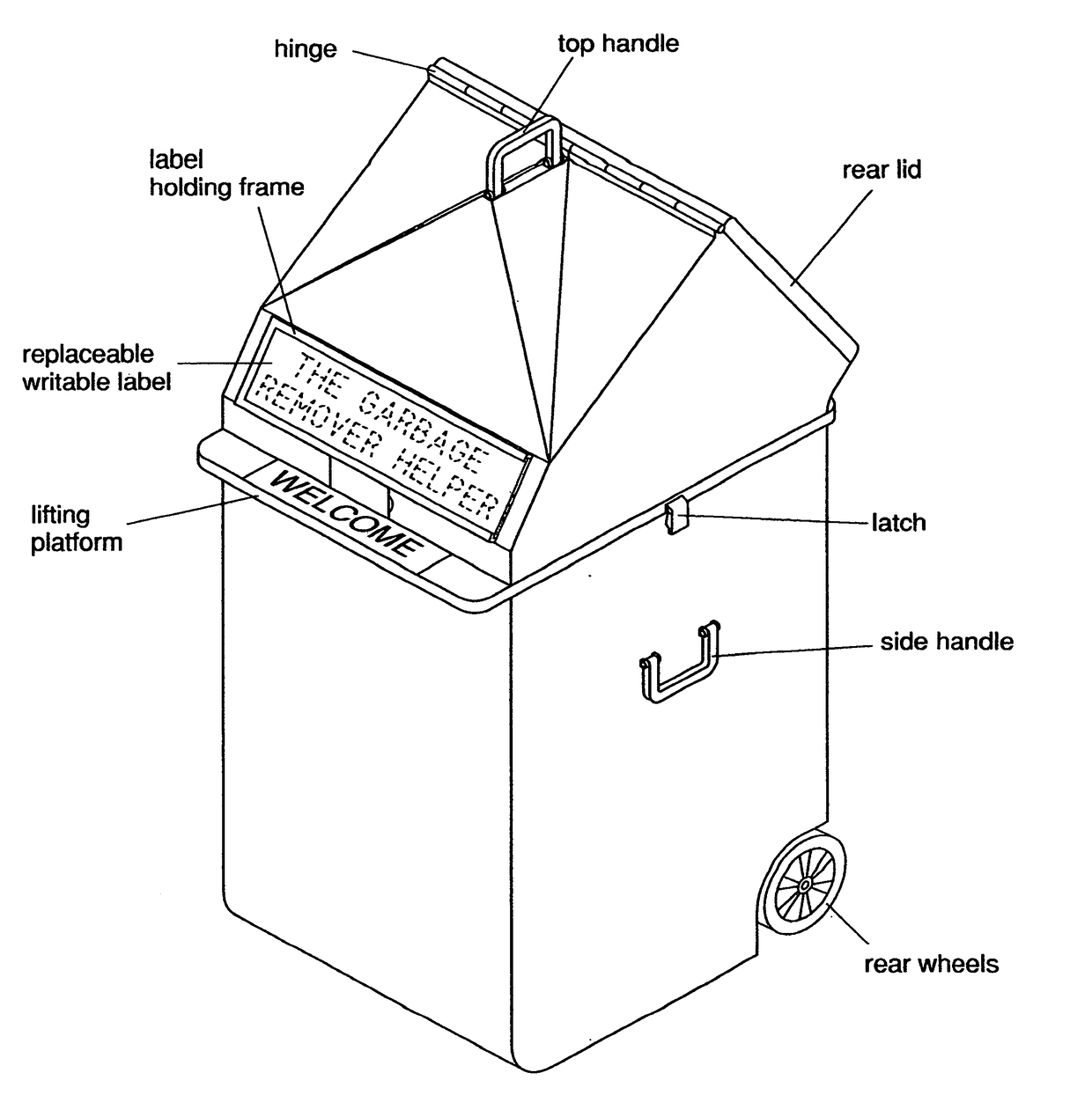
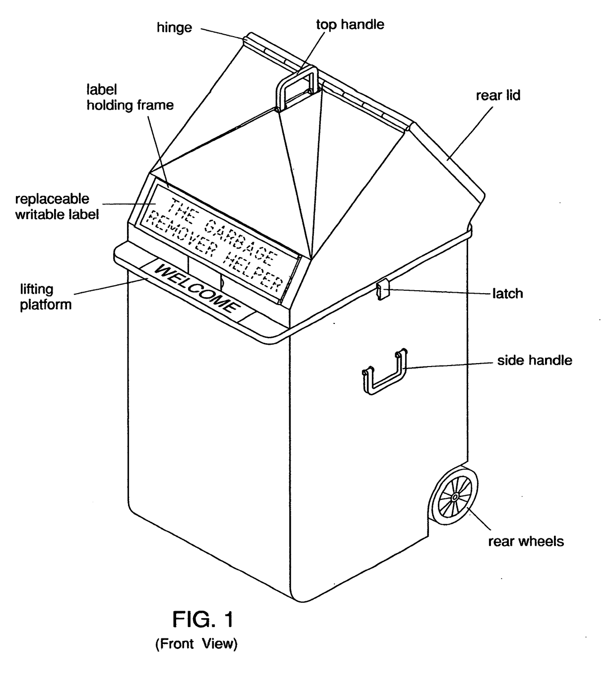
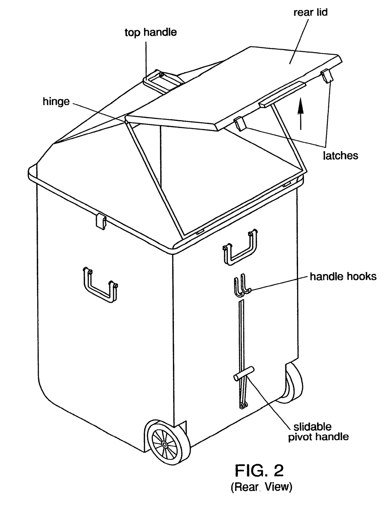
[0015]With reference now to the drawings, and in particular FIGS. 1 through 6 thereof, an example of the garbage bin device employing the principles and concepts of the present garbage bin device and generally designated by the reference number 10 will be described.

[0016]Referring to FIGS. 1 through 6, the garbage bin device 10 comprises a bottom section 20 having a front side 22 spaced apart from a back side 23, a left side 24 spaced apart from a right side 25, and a top side 26 spaced apart from a bottom side 27. A pair of rounded corners 29 is disposed proximal each of the front side 22, the bottom side 27, and the right side 25, and proximal each of the front side 22, the bottom side 27, and the left side 24. A first wheel recess 34 is provided proximal each of the bottom side 27, the back side 23, and the right side 25, and a second wheel recess 34 is provided proximal each of the bottom side 27, the back side 23, and the left side 24. A whee...


PUM


Abstract

The garbage bin device provides a lid section that can be totally unlatched from the bottom section, along with an overlap of the bottom section to avoid closing difficulties and to limit odor emanation. Pivoting handles are positioned to provide for balancing the device. A bottom opening with accordion door and t-handle operation provides for emptying the bin device as desired, whether through lid top or bottom side. A gable and arched top also provide for additional clearance for taller items. An indicia is provided for the lid section lid front, whether user or distributor supplied. A rear top overlap further protects against odor emanation. Latches assist in preventing animal invasion.

Description

BACKGROUND OF THE INVENTION[0001]While various types of garbage bins are known in the prior art, none have succeeded in solving all of the problems known to such bins. Many have wheels that are set outwardly from the bottom and do not navigate easily and correctly. Moreover, many garbage bins do not properly close and offer exuding refuse fumes that are not only offensive but attract various animals. Those garbage bins that do close and latch are typically very large, heavy, padlocked, and impossible to move without a truck or machine. Those that are more easily movable often do not have handles for ease of movement or allow a user access only through a large lid. The present garbage bin device solves these problems.FIELD OF THE INVENTION[0002]The present garbage bin device relates to garbage bins, and more particularly, to a personal garbage bin device that solves the existing problems of garbage bins.SUMMARY OF THE INVENTION[0003]The general purpose of the garbage bin device, desc...

Claims


Application Information

Patent Timeline
IPC IPC(8): B65F1/16B65F1/14
CPCB65F1/1615B65F1/1484B65F1/1623B65F1/1473B65F1/12B65F1/1607B65F2210/138
Inventor JOHNSON, LETRICIA DIANNE
Owner JOHNSON LETRICIA DIAHNE
Why Eureka
Try Eureka