Exhaust pump

Active Publication Date: 2013-06-27
EDWARDS JAPAN
View PDF8 Cites 8 Cited by
  • Summary
  • Abstract
  • Description
  • Claims
  • Application Information

AI Technical Summary

Benefits of technology

[0022]In the specific configuration of the exhaust pump in the first invention, as described above, a configuration is adopted wherein the gap that is formed between the lowermost stage rotor blades and the upstream end of the connecting opening portions has a dimension equal to or greater than a dimension that enables insertion, into the gap, of a tool for opening the connecting opening portions. Therefore, it becomes possible to open the connecting opening portions through insertion of the tool into such a gap, from the outer periphery of the cylindrical rotating member, while a short tool suffices for the opening process. In consequence, tool runout is unlikelier to occur during the opening processing of the connecting opening portions, which makes for good processability of the connecting opening portions. Also, a configuration is adopted wherein the opening regions between lowermost stage rotor blades and rotor blades that are adjacent to the lowermost stage rotor blades have a dimension equal to or greater than a dimension that enables insertion, into the opening regions, of a tool for opening the connecting opening portions. This configuration as well can elicit the same effect as above.
[0023]In the specific configuration of the exhaust pump in the second invention, as described above, a configuration is adopted wherein the plurality of connecting opening portions that are opened in the cylindrical rotating member are disposed to point symmetry with respect to a pump axis of the exhaust pump. As a result, the position of the center of gravity o

Problems solved by technology

Durability is thus problematic, in that the rotor (4) becomes likely to break from the vicinity of the connection ring section (unmarked with a reference numeral) where the connecting opening portions (4b) are formed.
Therefore, a long tool

Method used


Image

  • Exhaust pump
  • Exhaust pump
  • Exhaust pump

Examples


Example

[0040]Embodiments of the present invention are explained next with reference to drawings that accompany the specification.

[0041]1>>

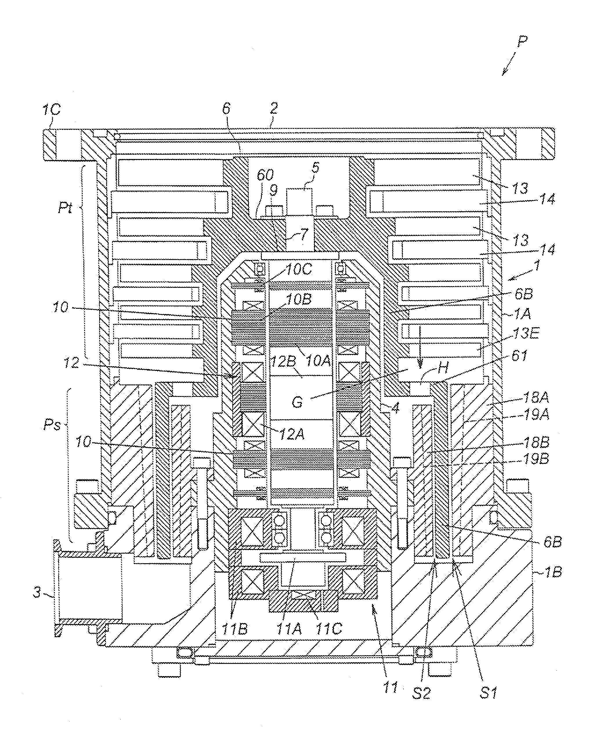
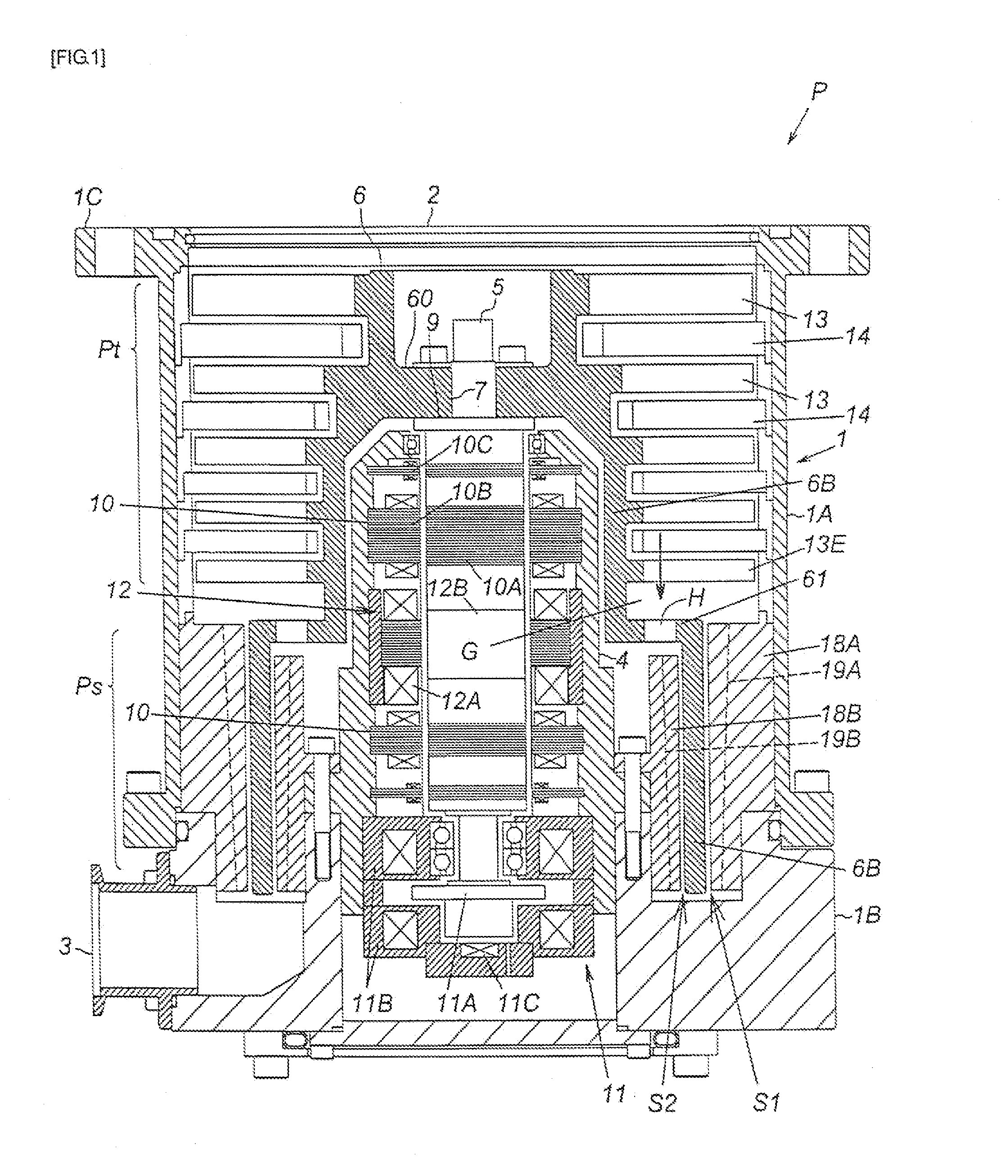
[0042]FIG. 1 is a cross-sectional diagram illustrating the overall configuration of an exhaust pump before the present invention is applied thereto. An exhaust pump P in the figure is used as gas evacuation means in, for instance, a process chamber in a semiconductor manufacturing apparatus, a flat panel display manufacturing apparatus, a solar panel manufacturing apparatus, and in other sealed chambers. The exhaust pump has an outer case 1, and in the interior thereof: a blade evacuation section Pt that evacuates gas by means of rotor blades 13 and stator blades 14; a thread groove evacuation section Ps that evacuates gas by way of thread grooves 19A and 19B; and a driving system of the foregoing.

[0043]The outer case 1 is a bottomed cylinder wherein a cylindrical pump case 1A and a bottomed cylindrical pump base 1B are integrally connected, by bolts, in...


PUM


Abstract

Provided is an exhaust pump that is suitable for enhancing durability, processability of connecting opening portions in a pump production stage, and evacuation performance. An exhaust pump includes: a cylindrical rotating member; a support unit of the cylindrical rotating member; a driving unit for rotationally driving the cylindrical rotating member; an outer cylindrical fixed member disposed so as to surround the outer periphery of the cylindrical rotating member; an inner cylindrical fixed member disposed so as to be surrounded by the inner periphery of the cylindrical rotating member; a helical outer thread groove exhaust passage provided between the cylindrical rotating member and the outer cylindrical fixed member; a helical inner thread groove exhaust passage provided between the cylindrical rotating member and the inner cylindrical fixed member; connecting opening portions that are opened in the cylindrical rotating member and that lead a part of gas existing in the vicinity of the outer periphery of the cylindrical rotating member towards the inner thread groove exhaust passage. A gap between an upstream end of the connecting opening portions and lowermost stage rotor blades provided at the outer periphery of the cylindrical rotating member which is located upstream of the connecting opening portions has a dimension equal to or greater than a dimension that enables insertion, into the gap, of a tool for opening the connecting opening portions.

Description

BACKGROUND OF THE INVENTION[0001]1. Field of the Invention[0002]The present invention relates to an exhaust pump that is used, as gas evacuation means or the like, in a process chamber of a semiconductor manufacturing apparatus, a flat panel display manufacturing apparatus or a solar panel manufacturing apparatus, and in other sealed chambers; more particularly, the present invention relates to an exhaust pump exhibiting enhanced durability, processability of connecting opening portions during the production stage of the pump, and also improved evacuation performance.[0003]2. Description of the Related Art[0004]One known method for enhancing the evacuation performance of an exhaust pump of a type where gas is evacuated by using a thread groove, but without modifying the overall size of the pump, is, for instance, the method disclosed in Japanese Utility Model Application Laid-open No. H5-38389.[0005]In this method, as illustrated in FIG. 1 of Japanese Utility Model Application Laid-...

Claims


Application Information

Patent Timeline
IPC IPC(8): F04D1/00
CPCF04D19/042F04D29/644F04D29/058F04D19/044F04D1/00F04D29/023F04D29/32F05D2230/10F04D19/04
Inventor OHTACHI, YOSHINOBUMAEJIMA, YASUSHITAKAADA, TSUTOMU
Owner EDWARDS JAPAN
Why Eureka
Try Eureka