Supercharge Your Innovation With Domain-Expert AI Agents!

Railcar end unit

a railcar and end unit technology, applied in the direction of buffers, railway components, draw gears, etc., can solve the problems of limiting the degree to which the draft gear can absorb forces, and the contents of the railcar, etc., and affecting the stability of the railcar. , the effect of reducing the degree of drafting gears

Active Publication Date: 2018-05-03
O RING SALES & SERVICE INC
View PDF3 Cites 7 Cited by
  • Summary
  • Abstract
  • Description
  • Claims
  • Application Information

AI Technical Summary

Benefits of technology

The railcar end unit effectively absorbs and isolates forces during buff and draft events, offering a longer stroke range than conventional draft gears while avoiding the leakage issues of hydraulic systems, thus enhancing performance and reducing maintenance costs.

Problems solved by technology

However, conventional draft gears and cushioning units have various deficiencies.
For instance, the short stroke of known draft gears greatly limits the degree to which draft gears can absorb forces and isolate the railcar (and its contents) from harmful forces.
Although known cushioning units provide greater stroke than draft gears, cushioning units are relatively complex and expensive.
Furthermore, cushioning units are prone to leaking hydraulic fluid and / or gases.
Such fluid and gas leakage greatly diminishes cushioning performance and can also produce an environmental hazard.
Fluid leakage associated with cushioning units also causes significant railcar downtime and results in expensive repair costs.

Method used


Image

  • Railcar end unit
  • Railcar end unit
  • Railcar end unit

Examples


Embodiment Construction

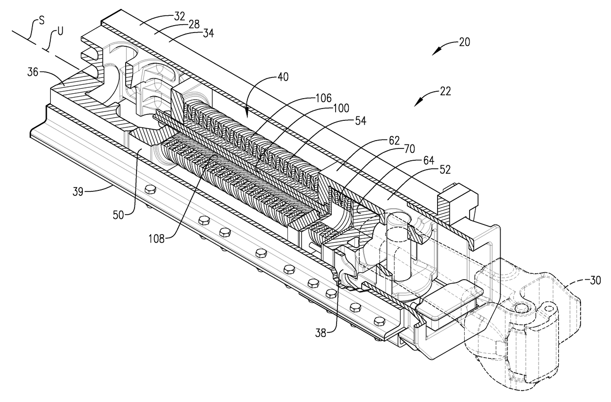
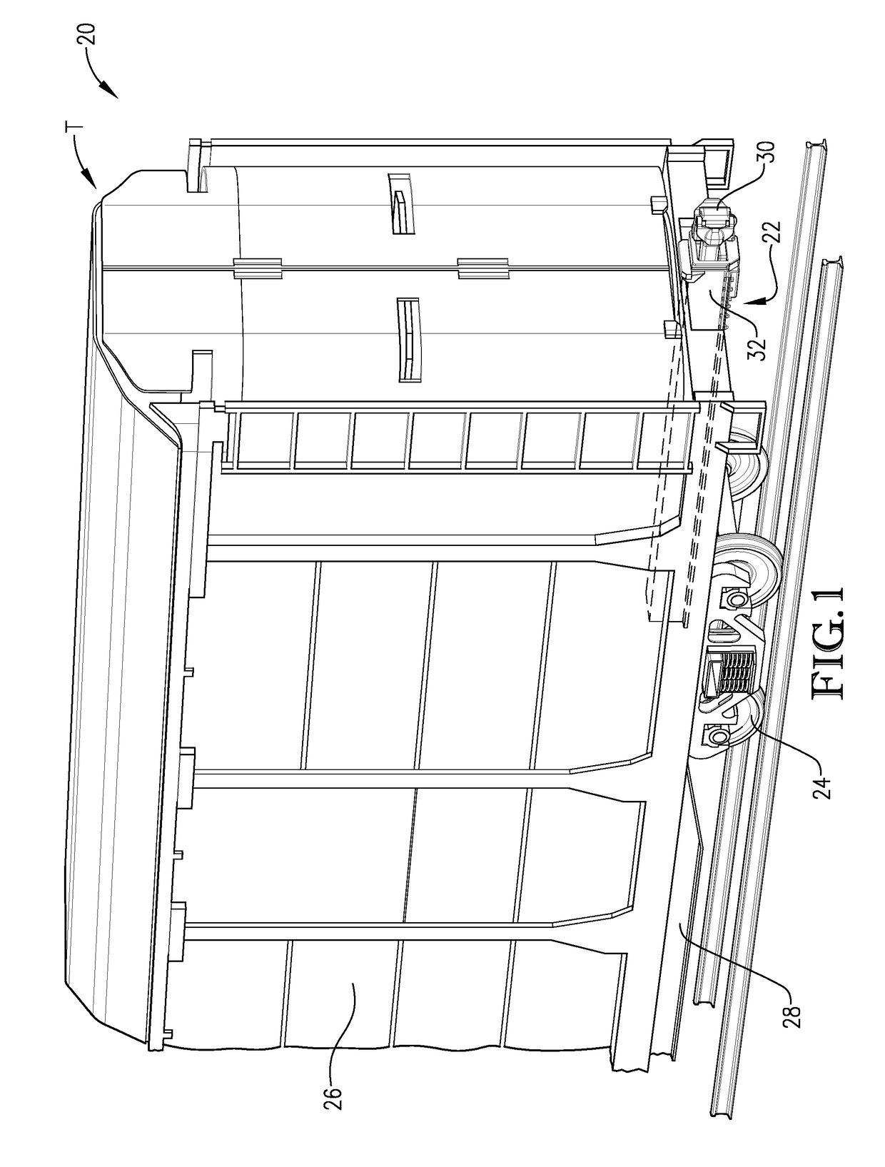
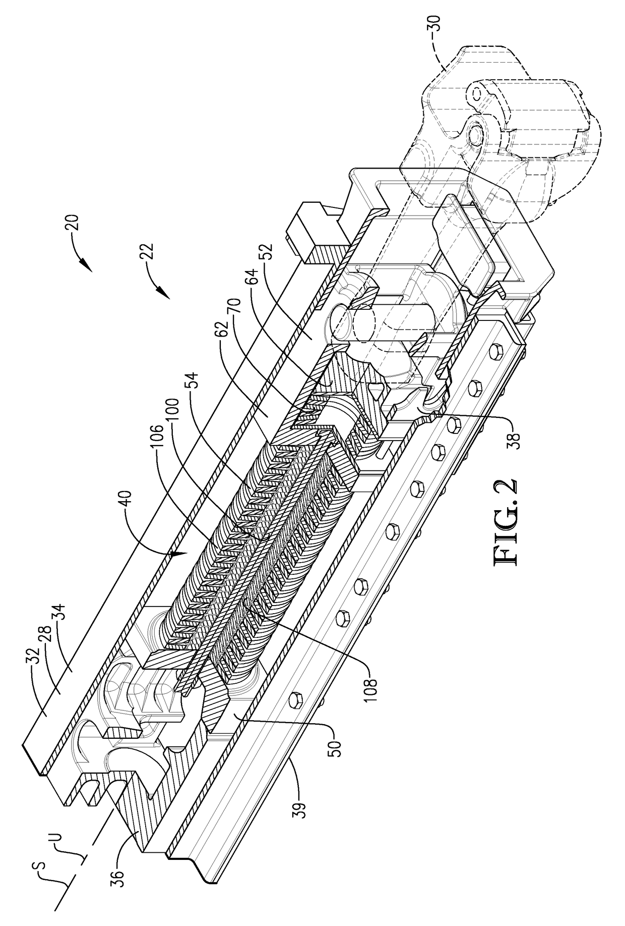
[0033]Turning initially to FIGS. 1-3, a railcar 20 is configured to be used with a string of other cars (not shown) as part of a train T to haul materials (not shown). As is customary, the railcar 20 is connected behind an adjacent rail car (not shown) and may also be connected in front of another adjacent railcar. As will be described in greater detail, the railcar 20 has a railcar end unit 22 that provides a cushioned connection between itself and one of the adjacent railcars. It will be understood that the adjacent railcars also preferably have end units that are similarly constructed to end unit 22. However, for some aspects of the present invention, an adjacent railcar could have an end unit with one of various configurations of a cushioning unit or a draft gear. The railcar 20 preferably includes trucks 24 and a car body 26 mounted on the trucks 24.

[0034]The car body 26 is designed to support the weight of materials contained therein. At the same time, the car body 26 also tra...


PUM


Abstract

A railcar end unit is operable to be mounted in a center sill between buff and draft sill stops. The buff and draft end bodies are configured to be shiftably mounted relative to the center sill to engage the respective sill stops and to shift axially relative to one another along a unit axis. The end unit includes a buff spring pack operably mounted between the end bodies and compressible along the unit axis from a neutral condition to a compressed condition.

Description

RELATED APPLICATION[0001]This application is a continuation of U.S. application Ser. No. 15 / 601,860, filed May 22, 2017, entitled RAILCAR END UNIT, which claims the benefit of U.S. Provisional Application Ser. No. 62 / 339,222, filed May 20, 2016, entitled RAILCAR END CUSHION, and U.S. Provisional Application Ser. No. 62 / 399,959, filed Sep. 26, 2016, entitled RAILCAR END CUSHION, each of which is hereby incorporated in its entirety by reference herein.BACKGROUND1. Field[0002]The present invention relates generally to railcar equipment. More specifically, embodiments of the present invention concern a railcar end unit mounted in the center sill of a railcar to provide cushioning between a coupler and the center sill.2. Discussion of Prior Art[0003]In the rail industry, various types of railcars commonly utilize a device to isolate the car from forces applied by adjacent cars. Of particular concern are axially-oriented forces referred to as draft forces (i.e., a pulling force applied to...

Claims


Application Information

Patent Timeline
Patent Type & Authority Applications(United States)
IPC IPC(8): B61G11/02B61G3/06B61G9/04B61G3/04B61G11/10
CPCB61G3/04B61G9/04B61G11/10B61G3/06B61G9/045B61G11/02B61G9/06
Inventor JOHNSON, KEVIN G.RALSTON, RICHARD URIAHJOHNSON, ANDREW ALLEN
Owner O RING SALES & SERVICE INC
Features
  • R&D
  • Intellectual Property
  • Life Sciences
  • Materials
  • Tech Scout
  • Unparalleled Data Quality
  • Higher Quality Content
  • 60% Fewer Hallucinations
Learn More