Drive force control device and method of controlling vehicle

a technology of control device and driving force, which is applied in the direction of control device, external condition input parameters, control device, etc., can solve the problem that the effect of stabilizing the behavior of the vehicle may not always be fully demonstrated, and achieve the effect of stabilizing the behavior of the vehicl

Active Publication Date: 2018-05-17
JTEKT CORP
View PDF7 Cites 6 Cited by
  • Summary
  • Abstract
  • Description
  • Claims
  • Application Information

AI Technical Summary

Benefits of technology

[0006]It is an object of the present invention to provide a drive force control device that is capable of stabilizing the behavior of a vehicle compared to the case where drive forces to be transferred to right and left wheels are controlled such that the actual rotational speeds approximate target rotational speeds that match a steering angle, and a method of controlling a vehicle.
[0021]With the drive force control device and the method of controlling a vehicle according to the aspects described above, it is possible to stabilize the behavior of the vehicle compared to the case where drive forces to be transferred to right and left wheels are controlled such that the actual rotational speeds approximate target rotational speeds that match a steering angle.

Problems solved by technology

However, if the steering angle becomes larger than an angle at which the vehicle is able to turn while keeping a stable travel state, such as in the case where the steering wheel is operated greatly during a turn at a high speed, for example, the effect in stabilizing the behavior of the vehicle may not always be fully demonstrated.

Method used


Image

  • Drive force control device and method of controlling vehicle
  • Drive force control device and method of controlling vehicle
  • Drive force control device and method of controlling vehicle

Examples


first embodiment

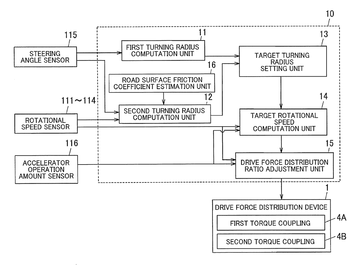
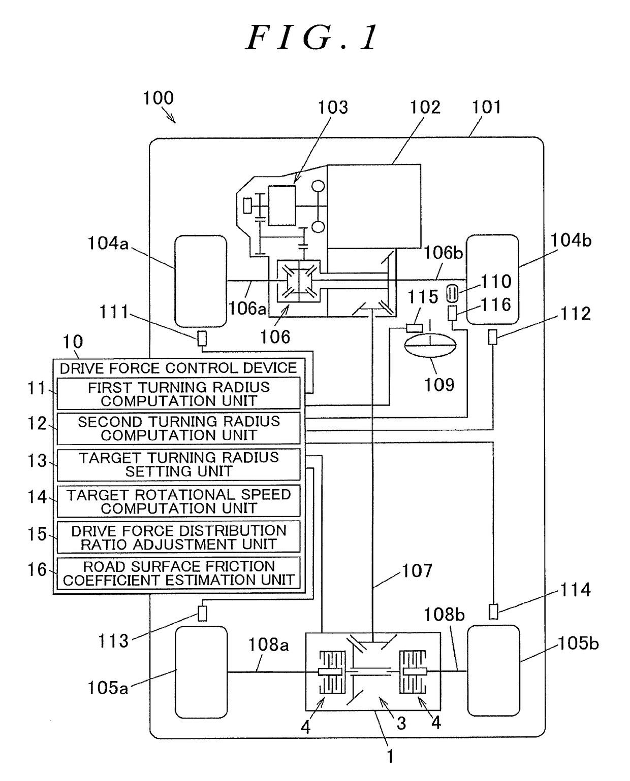
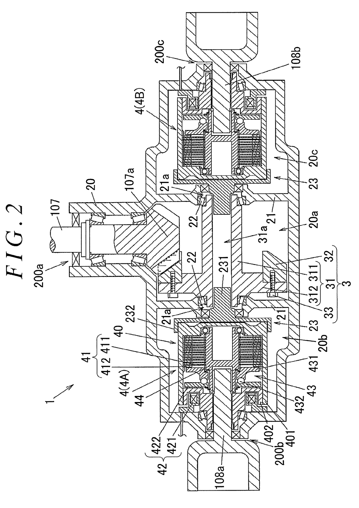
[0030]the present invention will be described with reference to FIGS. 1 to 4.

[0031]FIG. 1 is a schematic diagram illustrating a schematic example of the configuration of a four-wheel-drive vehicle according to a first embodiment of the present invention. As illustrated in FIG. 1, a four-wheel-drive vehicle 100 includes a vehicle body 101, an engine 102, a transmission 103, right and left front wheels 104b and 104a (right and left wheels on the front side), and right and left rear wheels 105b and 105a (right and left wheels on the rear side). The engine 102 serves as a drive source that generates torque for travel. The right and left front wheels 104b and 104a serve as a pair of right and left main drive wheels to which a drive force of the engine 102 is always transferred. The right and left rear wheels 105b and 105a serve as a pair of right and left auxiliary drive wheels to which a drive force of the engine 102 is transferred intermittently in accordance with the travel state.

[003...


PUM


Abstract

A drive force control device, which controls a drive force distribution device that distributes a drive force to right and left rear wheels at variable distribution ratios, computes a steering angle-based turning radius determined in accordance with a steering angle, computes a limit turning radius, which is a minimum value of the turning radius with which the vehicle is turnable while keeping a stable travel state, in accordance with a vehicle speed, sets the larger one of the steering angle-based turning radius and the limit turning radius as a target turning radius, computes target rotational speeds for the right and left rear wheels on the basis of the target turning radius and the vehicle speed, and adjusts the ratios of distribution of the drive force to the right and left rear wheels such that actual rotational speeds of the right and left rear wheels approximate the target rotational speeds.

Description

INCORPORATION BY REFERENCE[0001]The disclosure of Japanese Patent Application No. 2016-220614 filed on Nov. 11, 2016 including the specification, drawings and abstract, is incorporated herein by reference in its entirety.BACKGROUND OF THE INVENTION1. Field of the Invention[0002]The present invention relates to a drive force control device that can distribute a drive force of a drive source to right and left wheels of a vehicle at variable distribution ratios, and to a method of controlling a vehicle.2. Description of the Related Art[0003]There has hitherto been known a control device described in Japanese Patent Application Publication No. 2014-40852 (JP 2014-40852 A) as a control device that controls a drive force transfer device that transfers a drive force to right and left wheels of a vehicle.[0004]The drive force transfer device described in JP 2014-40852 A includes a turning radius estimation unit, a target slip angle computation unit, a target rotational speed computation uni...

Claims


Application Information

Patent Timeline
Patent Type & Authority Applications(United States)
IPC IPC(8): B60K17/16B60W40/072B60W30/045B60K23/04B60W40/068B60K17/02
CPCB60K17/20B60W40/072B60W30/045B60K23/04B60W40/068B60K17/02B60K17/34B60K2023/043B60W2540/10B60W2520/10B60K17/348B60K17/35B60K17/351B60K2023/0858B60W2540/18B60W2720/406B60W2552/30B60W2552/40
Inventor NAGAYAMA, GOKODAMA, AKIRA
Owner JTEKT CORP
Why Eureka
Try Eureka