Expansion Joint Seal System

a technology of expansion joint and seal system, which is applied in the direction of building components, building insulations, constructions, etc., can solve the problems of requiring replacement of concrete, spalling of concrete, and insufficient protection of the surface of the construction panel perpendicular to the exposed surfa

Active Publication Date: 2018-05-31
SCHUL INT COMPANY
View PDF0 Cites 53 Cited by
  • Summary
  • Abstract
  • Description
  • Claims
  • Application Information

AI Technical Summary

Benefits of technology

The present invention introduces an expansion joint seal system that offers both fire protection and flexible insulation for building panels. This helps prevent damage from heat and pollutants, making it easier to maintain the quality of construction.

Problems solved by technology

The technical problem presented in this patent text relates to providing effective protection against fire damages to construction panels that include gaps or joints between them. Existing techniques involve either forming a protective layer on top of the existing seal or adding extra materials like expandable foams or intumescents to address potential fire risks. However, there remains a lack of effectiveness in ensuring both long life and resistance to high temperatures. Therefore, there is a need for an improved expansion joint seal solution that provides better insulation and longer lifespan while still being able to handle extreme temperatures without compromising its performance.

Method used


Image

  • Expansion Joint Seal System
  • Expansion Joint Seal System
  • Expansion Joint Seal System

Examples


Embodiment Construction

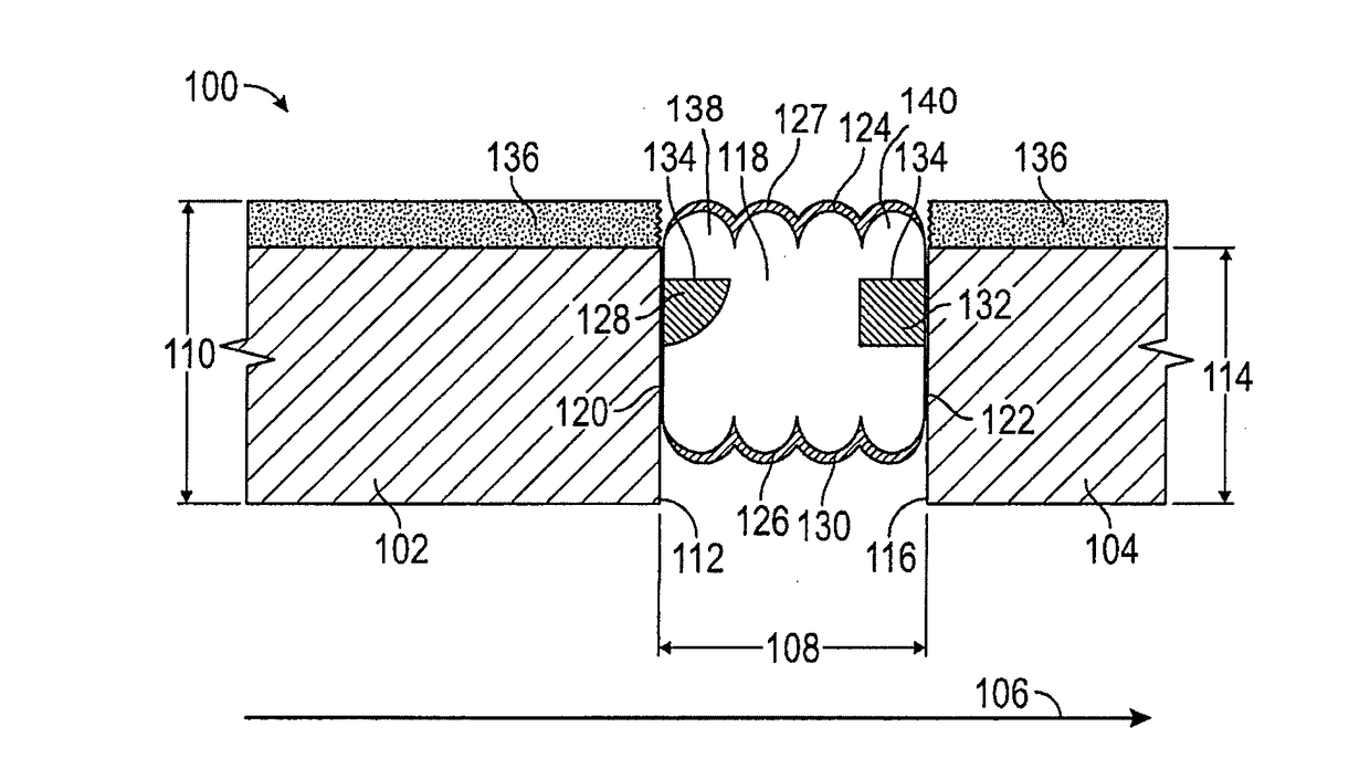
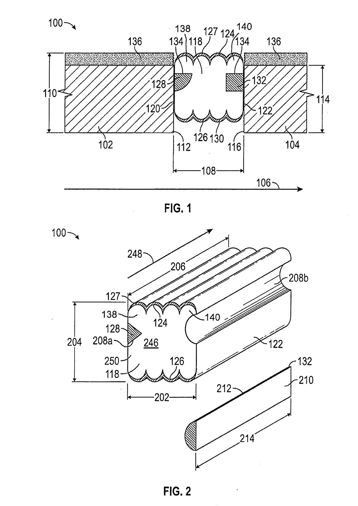
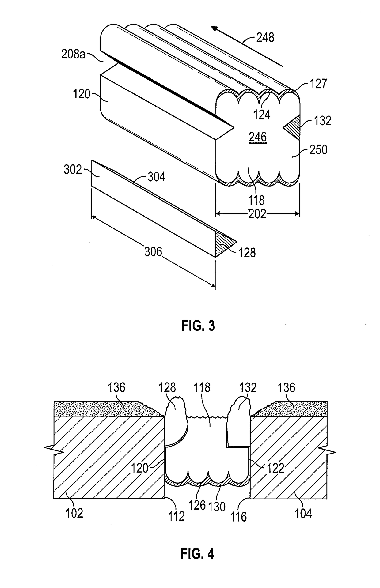
[0030]The expansion joint system 100 of the present disclosure includes a body of compressible foam 118, at least one intumescent member 128, and may include at least one elastomer layer 127 which provide an integral, but flexible, expansion joint system which has reduced susceptibility to shearing and delamination while providing fire-protection to substrate upper portions, edges and adjacent surfaces. Referring to FIGS. 1-3 and 5, the expansion joint system 100 is illustrated when imposed under compression between a first substrate 102 and a second substrate 104, typically occurring at a joint 103 between two substrates 102, 104. A side view of the expansion joint system of the present disclosure when installed between two substrates to extend above the top of the adjacent substrates is illustrated in FIG. 1. A side view of an expansion joint system of the present disclosure when installed between two substrates at an alternative location well below the top of the adjacent substra...


PUM


Abstract

An expansion joint seal system which includes intumescent to protect uncoated edges of substrates. A fire rated compressed expansion joint sealant is provided having an intumescent proximate, but below the water-resistant top of the fire-retardant foam, so that when exposed to fire, the intumescent expands to protect the exposed vertical surface of the adjacent concrete substrate. The end of the concrete is therefore protected in a manner which does not require joint overlap between the horizontal fire resistant coating and the compressible sealant.

Description


Claims


Application Information

Patent Timeline
Owner SCHUL INT COMPANY
Why Eureka
Try Eureka