Failure diagnosis device and failure diagnosis method

a failure diagnosis and failure technology, applied in the direction of instrumentation, programme control, force/torque/work measurement apparatus, etc., can solve the problems of one-off abnormal value, sudden stoppage of the robot hand during its operation, and abrupt application of load to the motion axis, so as to improve the accuracy of failure diagnosis and generate large amounts of investment and maintenance costs

Active Publication Date: 2018-06-07
NISSAN MOTOR CO LTD
View PDF25 Cites 2 Cited by
  • Summary
  • Abstract
  • Description
  • Claims
  • Application Information

AI Technical Summary

Benefits of technology

[0005]In the meantime, a method of cooperating with a production management system can be thought as a method of acquiring emergency stop information on a facility. However, construction of the production management system may generate large amounts of investments and maintenance costs.
[0006]One or more embodiments of the present invention provides a failure diagnosis device and a method thereof, which are capable of improving failure diagnosis accuracy by eliminating effects of one-off abnormal values, and of diagnosing a failure with a low-cost system configuration.

Problems solved by technology

However, in case of an emergency shutdown of a facility, the robot hand is suddenly stopped during its operation and an abrupt load is applied to its motion axis.
As a consequence, a value of the disturbance torque changes significantly and causes a one-off abnormal value.
Continued operation of the failure diagnosis by using the certain set threshold without eliminating such effects of one-off abnormal values may lead to frequent occurrence of diagnoses as being abnormal in spite of being nominal as a matter of fact, thus causing deterioration in failure diagnosis accuracy.
However, construction of the production management system may generate large amounts of investments and maintenance costs.

Method used


Image

  • Failure diagnosis device and failure diagnosis method
  • Failure diagnosis device and failure diagnosis method
  • Failure diagnosis device and failure diagnosis method

Examples


Embodiment Construction

[0012]Embodiments of the present invention will be described below with reference to the drawings. In the description of the drawings, the same constituents are denoted by the same reference signs and explanations thereof are omitted. In embodiments of the invention, numerous specific details are set forth in order to provide a more thorough understanding of the invention. However, it will be apparent to one of ordinary skill in the art that the invention may be practiced without these specific details. In other instances, well-known features have not been described in detail to avoid obscuring the invention.

[Configuration of Failure Diagnosis System]

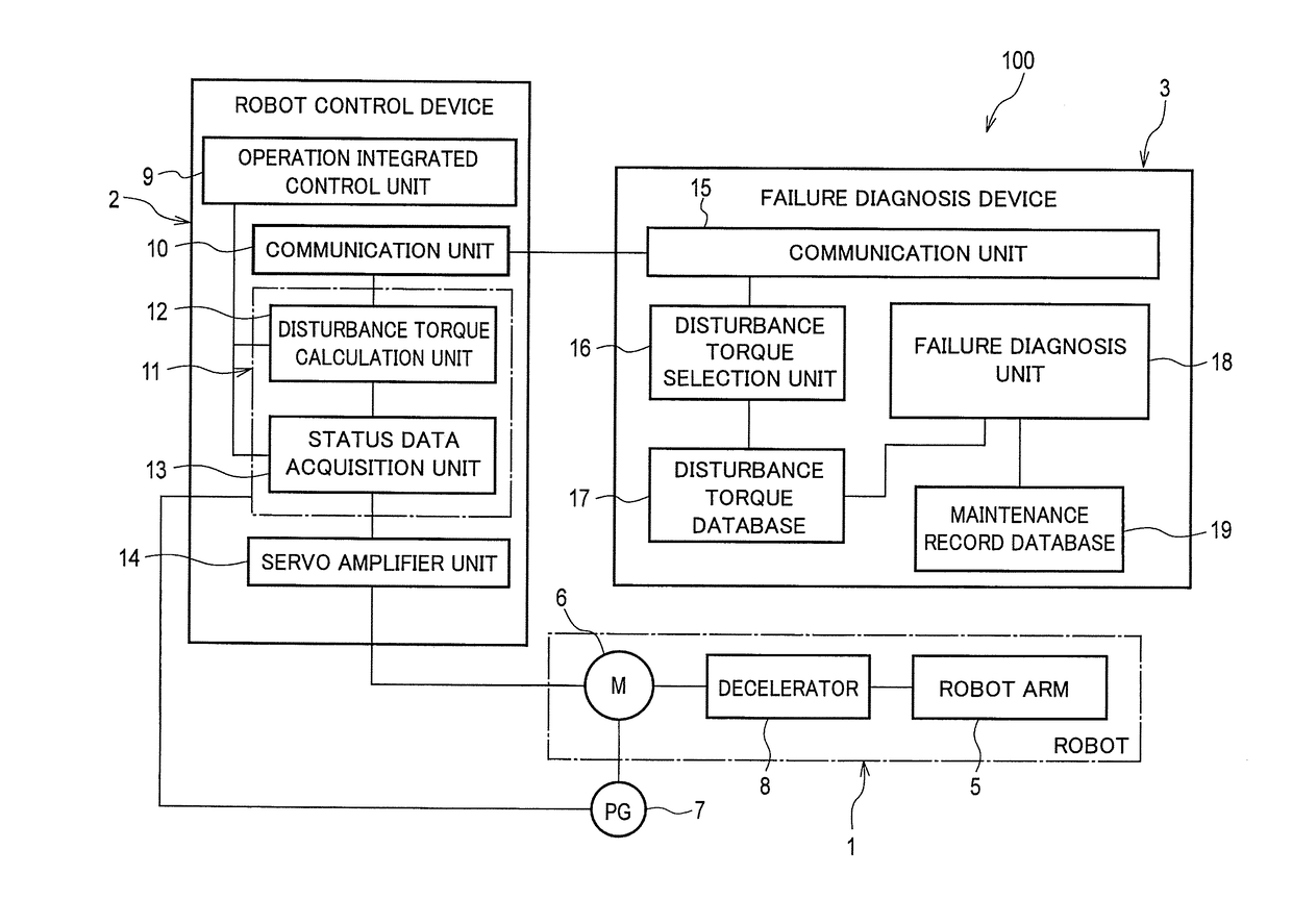
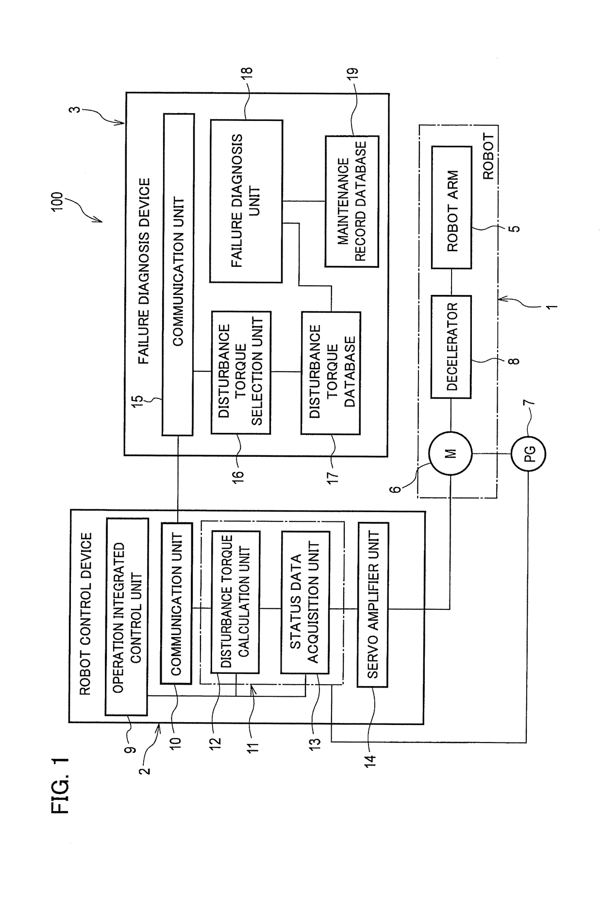
[0013]FIG. 1 is a block diagram showing a configuration of a failure diagnosis system including a failure diagnosis device according to one or more embodiments of the present invention. As shown in FIG. 1, a failure diagnosis system 100 of one or more embodiments of the present invention is formed from a robot 1, a robot control device ...


PUM

PropertyMeasurementUnit
disturbance torqueaaaaaaaaaa
weightaaaaaaaaaa
velocityaaaaaaaaaa

Abstract

A failure diagnosis device applicable to a mechanical device provided with a motor as a source to drive a motion axis, and configured to acquire a moving position of the motion axis and a disturbance torque value applied to the motion axis every predetermined period, and to diagnose that a failure is occurring when the disturbance torque value is larger than a failure determination threshold, includes a disturbance torque selector configured to calculate a change from a reference value of each of the acquired disturbance torque values, and to accumulate the disturbance torque values except each disturbance torque value having the change from the reference value equal to or larger than a predetermined threshold, and a failure diagnosis unit configured to diagnose a failure of the mechanical device by using the disturbance torque values accumulated by the disturbance torque selector.

Description

BACKGROUNDTechnical Field[0001]The present invention relates to a failure diagnosis device applicable to a mechanical device provided with a motor as a source to drive a motion axis, and to a method thereof.Related Art[0002]Patent Literature 1 has been disclosed as a conventional failure diagnosis method applicable to an articulated industrial robot. In the failure diagnosis method disclosed in Patent Literature 1, a moving position of a joint axis of a robot and disturbance torque applied to the joint axis are detected every predetermined period while the robot is in operation, and an average value of the disturbance torque is obtained for each detected moving position. Then, the average value is compared with a set threshold and the robot is diagnosed as having an abnormality or a failure when the average value exceeds the set threshold. As described above, the conventional technique has been designed to diagnose a failure based on determination as to whether or not the disturbanc...

Claims


Application Information

Patent Timeline
Patent Type & Authority Applications(United States)
IPC IPC(8): B25J19/06B25J13/08G01L3/00G01L5/00
CPCB25J19/06B25J13/085G01L3/00G01L5/00B25J9/1674G05B19/406G05B2219/37525G05B2219/37536G05B2219/37624G05B2219/39355B25J19/0095
Inventor KUNO, MASAKIURAKAWA, TOSHIMICHI
Owner NISSAN MOTOR CO LTD
Why Eureka
Try Eureka