Modular Unmanned Aerial System with Multi-Mode Propulsion

a technology of unmanned aerial systems and modules, applied in the direction of power plant fuel tanks, vertical landing/take-off aircraft, transportation and packaging, etc., can solve the problems of reduced payload carrying capacity, reduced flying range, and inefficient flight operations, etc., to achieve the effect of expanding the effective flight range of the uas

Inactive Publication Date: 2018-06-07
NASA
View PDF0 Cites 34 Cited by
  • Summary
  • Abstract
  • Description
  • Claims
  • Application Information

AI Technical Summary

Benefits of technology

[0005]An Unmanned Aerial System (UAS) as described herein may be configured to provide the above-noted distributed aerial presence using one or more Unmanned Aerial Vehicle (UAV) modules as set forth herein. The UAS and / or the individual UAV modules of may deliver parcels or transport other payloads over an expanded flight range, or may optionally perform dedicated flight missions such as scientific data collection, search and rescue operations, or intelligence, reconnaissance and surveillance (ISR) missions. The present approach may involve the coordinated use of multiple UAV “child” modules that optionally dock or link to each other or to a UAV “parent” module, e.g., in a wingtip-to-wingtip manner. As a result, the effective flight range of the UAS may be expanded, with a possible sharing of energy taking place between linked modules during certain flight modes.

Problems solved by technology

While relatively lightweight, the use of fixed rotors may result in inefficient flight operations, reduced flying ranges, and / or lower payload-carrying capabilities.

Method used


Image

  • Modular Unmanned Aerial System with Multi-Mode Propulsion
  • Modular Unmanned Aerial System with Multi-Mode Propulsion
  • Modular Unmanned Aerial System with Multi-Mode Propulsion

Examples


Embodiment Construction

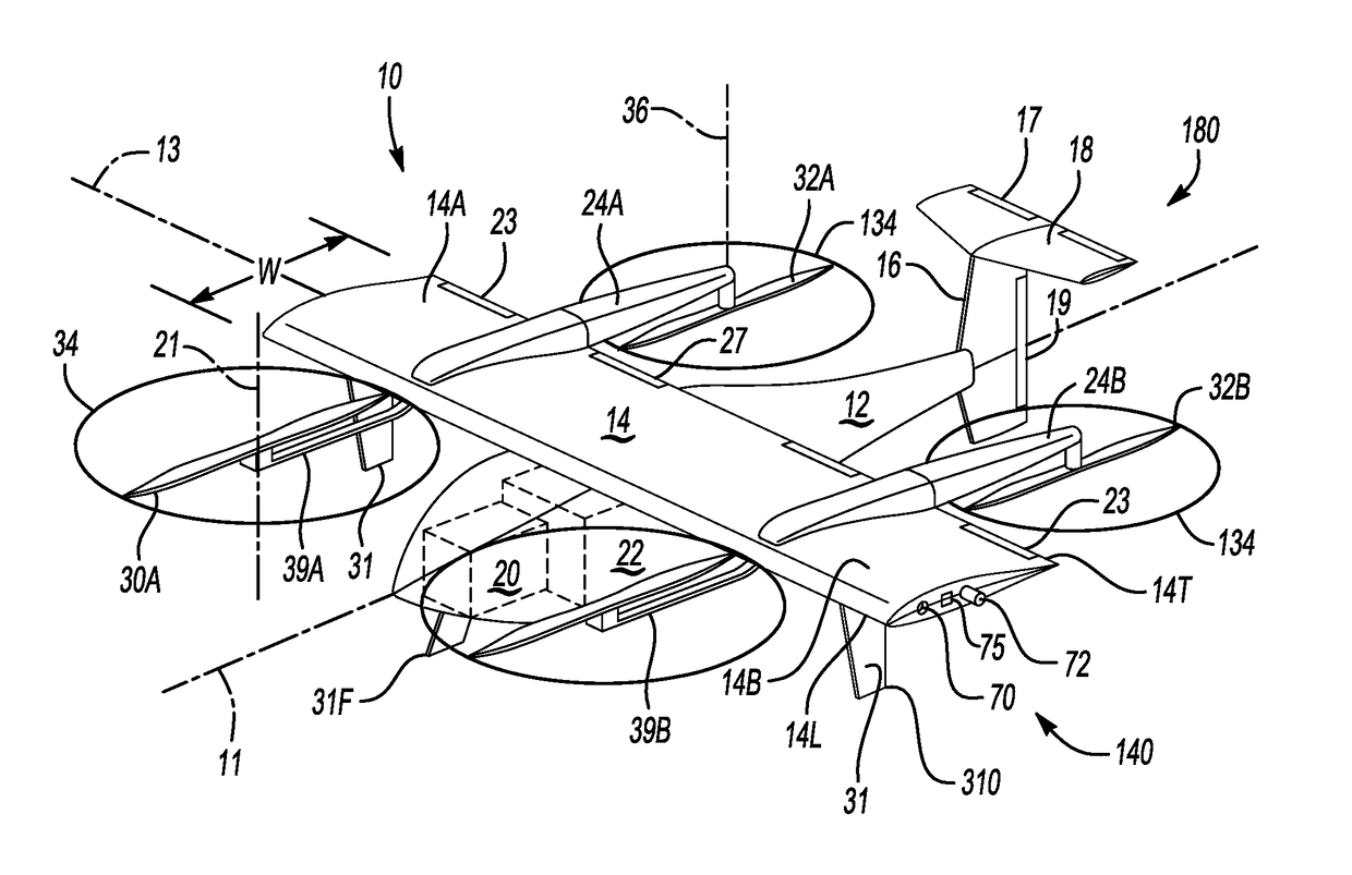
[0027]For purposes of description herein, the terms “upper,”“above”, “lower,”“right,”“left,”“rear,”“aft”, “front,”“fore”, “vertical,”“horizontal,” and derivatives thereof shall relate to the invention as oriented in FIG. 1. However, various alternative orientations and step sequences are possible, except where expressly specified to the contrary. The specific devices and processes illustrated in the drawings and described in the following specification are intended as exemplary embodiments of the structure or processes as defined in the appended claims. Hence, specific dimensions and other physical characteristics relating to the representative embodiments disclosed herein are not limiting, unless the claims expressly state otherwise.

[0028]With reference to the drawings, wherein like reference numbers refer to the same or similar components throughout the several views, an Unmanned Aerial Vehicle (UAV) module 10 is depicted schematically in FIG. 1 in a vertical takeoff and landing (...


PUM


Abstract

A modular Unmanned Aerial System (UAS) includes an Unmanned Aerial Vehicle (UAV) parent module and UAV child modules. A main wing extends from a respective fuselage of the modules. The UAS includes docking mechanisms coupled to wingtips of the main wings. The child modules dock with the wingtips of the parent or an adjacent child module. Docking forms a linked-flight configuration, with undocking and separation from the parent or adjacent child module achieving an independent-flight configuration. The modules have booms arranged transverse to the main wings and parallel to the longitudinal axis, as well as front and rear rotors / propellers. The front and rear propellers have axes of rotation that are normal to a plane of the longitudinal axis in a vertical takeoff and landing (VTOL) configuration, with the axis of rotation of the rear propellers parallel to the longitudinal axis in a forward-flight configuration.

Description

CROSS-REFERENCE TO RELATED PATENT APPLICATIONS[0001]This patent application claims the benefit of and priority to U.S. Provisional Patent Application No. 62 / 429,091, filed on Dec. 2, 2016, the contents of which are hereby incorporated by reference in their entirety.STATEMENT REGARDING FEDERALLY SPONSORED RESEARCH OR DEVELOPMENT[0002]The invention described herein was made by employees of the United States Government and may be manufactured and used by or for the Government of the United States of America for governmental purposes without the payment of any royalties thereon or therefor.BACKGROUND OF THE INVENTION[0003]Unmanned Aerial Vehicle (UAV)-based services for commercial, private, and government applications have received heightened attention in recent years due largely to advancements in key supporting technologies. Corporate entities in particular continue to aggressively develop UAV-based delivery systems with the expectation that market demand for such services will includ...

Claims


Application Information

Patent Timeline
Patent Type & Authority Applications(United States)
IPC IPC(8): B64C37/02B64C39/02B64C29/00B64C3/00
CPCB64C37/02B64C39/024B64C29/0033B64C3/00B64C2201/042B64C2201/104B64C2201/108B64C2201/146B64C9/00B64C2201/128B64D37/04B64C2211/00B64U10/25B64U30/10B64U2201/102B64U30/20B64U50/19B64U50/13B64U2101/60B64U2201/20
Inventor PATTERSON, MICHAEL D.QUINLAN, JESSE R.FREDERICKS, WILLIAM J.
Owner NASA
Why Eureka
Try Eureka