Handling Perspective Magnification in Optical Flow Proessing

a technology of optical flow and perspective magnification, which is applied in the field of optical flow processing, can solve the problems of inability to realize real-time optical flow processing, inability to accurately match, and computational complexity of sifting,

Active Publication Date: 2018-06-28
TEXAS INSTR INC
View PDF0 Cites 16 Cited by
  • Summary
  • Abstract
  • Description
  • Claims
  • Application Information

AI Technical Summary

Problems solved by technology

That is, given two consecutive images, a query image and a reference image, the problem is to find the best matching position of a pixel in the query image in the reference image.
If perspective changes are not accounted for in searching for the best matching pixel, the match may be inaccurate and the inaccuracy may propagate to algorithms that use the optical flow information.
However, SIFT is computationally complex and may be not suitable for real-time optical flow processing in ADAS.

Method used


Image

  • Handling Perspective Magnification in Optical Flow Proessing
  • Handling Perspective Magnification in Optical Flow Proessing
  • Handling Perspective Magnification in Optical Flow Proessing

Examples


Embodiment Construction

[0020]Specific embodiments of the disclosure will now be described in detail with reference to the accompanying figures. Like elements in the various figures are denoted by like reference numerals for consistency.

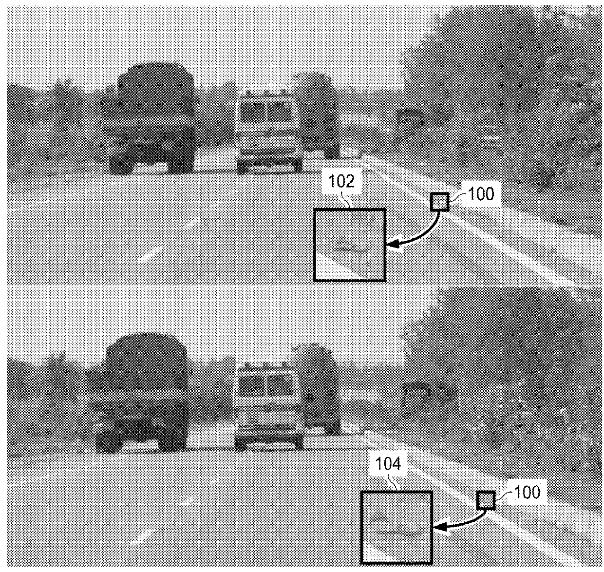
[0021]A moving object in the real world has a three dimensional (3D) motion. A camera capturing a moving object captures a two dimensional (2D) projection of the actual 3D motion. The 2D motion of a moving object can be determined by observing consecutive captured images of the object. The 2D motion of an image pixel from image to image is referred to as the optical flow of the pixel and is defined as the displacement vector of the pixel between two consecutive images. For dense optical flow, the optical flow of each pixel is determined.

[0022]As previously mentioned, determination of the optical flow of a pixel is fundamentally a “best correspondence” finding problem. That is, given two consecutive images, a query image and a reference image, the problem is to find the best...


PUM


Abstract

A method of optical flow estimation is provided that includes identifying a candidate matching pixel in a reference image for a pixel in a query image, determining a scaled binary pixel descriptor for the pixel based on binary census transforms of neighborhood pixels corresponding to scaling ratios in a set of scaling ratios, determining a scaled binary pixel descriptor for the candidate matching pixel based on binary census transforms of neighborhood pixels corresponding to scaling ratios in the set of scaling ratios, and determining a matching cost of the candidate matching pixel based on the scaled binary pixel descriptors.

Description

CROSS-REFERENCE TO RELATED APPLICATIONS[0001]This application claims benefit of India Provisional Patent Application Serial No. 201641043792, filed Dec. 22, 2016, which is incorporated herein by reference in its entirety.BACKGROUND OF THE DISCLOSUREField of the Disclosure[0002]Embodiments of the present disclosure generally relate to optical flow processing, and more specifically relate to handling perspective magnification in optical flow processing.Description of the Related Art[0003]Advanced driver assistance systems, or ADAS, are becoming increasingly commonplace in automobiles. These systems provide the driver with the information about the surroundings and potentially automatically intervene with the process of driving to prevent accidents and road fatalities. Three dimensional (3D) scene understanding using image sensors is an elementary step in building this scene understanding. Scene motion understanding using optical flow is a common technique that provides accurate motion...

Claims


Application Information

Patent Timeline
Patent Type & Authority Applications(United States)
IPC IPC(8): G06K9/00H04N19/20H04N19/513H04N19/523H04N19/53H04N19/56G06T7/269G06T5/20G06T5/00G06V10/40
CPCG06K9/00791H04N19/20H04N19/521H04N19/523G06T5/002H04N19/56G06T7/269G06T5/20H04N19/53G06T2207/30252G06T7/246G06V20/56G06V10/94G06V10/62G06V10/40G06V10/467G06V10/761G06F18/22
Inventor GARUD, HRUSHIKESH TUKARAMMATHEW, MANUNAGORI, SOYEB NOORMOHAMMED
Owner TEXAS INSTR INC
Why Eureka
Try Eureka