
Inflatable stretcher

a technology of inflatable stretcher and sling, which is applied in the field of inflatable stretcher, can solve the problems of increasing the time it takes to lift up the lying patient, the weight of the patient lying on the inflatable stretcher is not always uniformly distributed over the whole bottom surface of the inflatable stretcher, and it is relatively difficult to manually move the immovable patient. , to achieve the effect of reducing the time of inflating, and reducing the risk of falling o

Active Publication Date: 2018-07-19
CAREMED SUPPLY
View PDF0 Cites 5 Cited by
  • Summary
  • Abstract
  • Description
  • Claims
  • Application Information

AI Technical Summary

Benefits of technology

The present invention provides an improved inflatable stretcher that overcomes disadvantages of prior art stretches. The stretcher has multiple perforations on the lower cover that match the shape of the human body, allowing for increased air lifting force. It also has two air inlets, making it more convenient for use. The stretcher is designed for carrying patients and easily transferring them to other support surfaces. It has flow openings that create an increased air lifting force at the patient's hips. The stretcher can be inflated from one side or both sides, and it has holding elements to keep the air hoses in place during inflation. This prevents separation of the hoses from the stretcher.

Problems solved by technology

In the past, it is relatively difficult to manually move an immovable patient, such as an injured person in an accident, an aged person or other disabled persons, onto a bed or a stretcher that provides a support surface, and at least two or three nursing personnel are needed to laboriously complete this work.
However, the weight of the patient lying on the inflatable stretcher is not always uniformly distributed over the whole bottom surface of the inflatable stretcher.
Therefore, some areas of the conventional inflatable stretcher that are compressed by the lying patient will require more time to be lifted up when compared with other areas that are not compressed by the patient's weight.
That is, with the conventional inflatable stretcher, a longer time is needed to lift up the patient from the inflatable stretcher.

Method used


Image

  • Inflatable stretcher
  • Inflatable stretcher
  • Inflatable stretcher

Examples


Embodiment Construction

[0035]The present invention will now be described with some preferred embodiments thereof and by referring to the accompanying drawings.

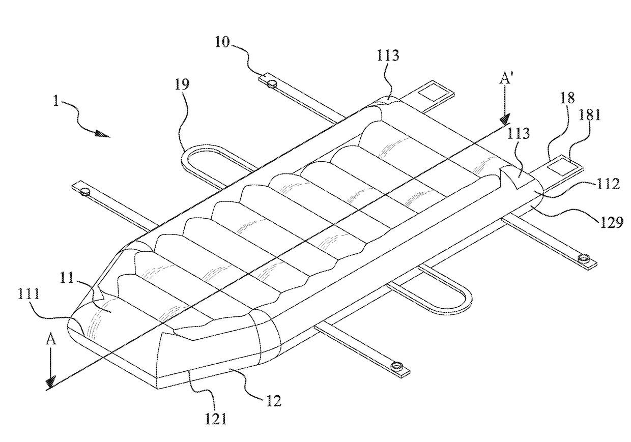
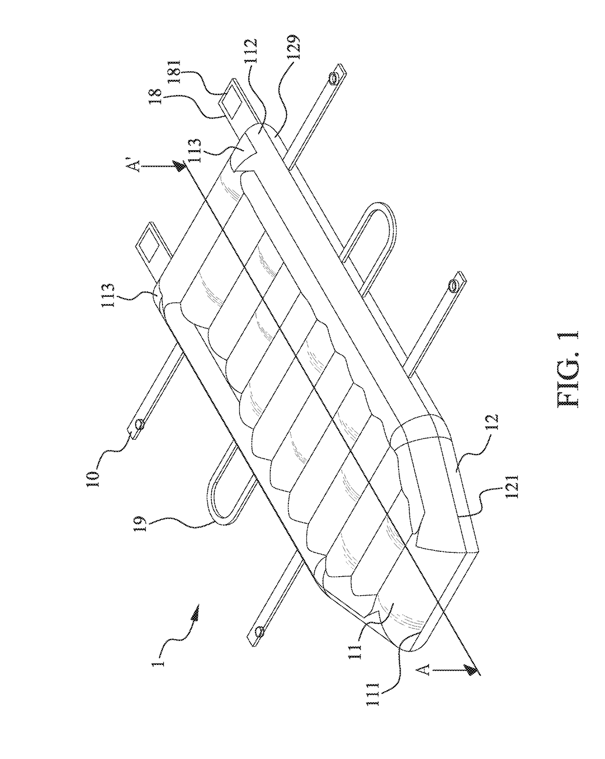
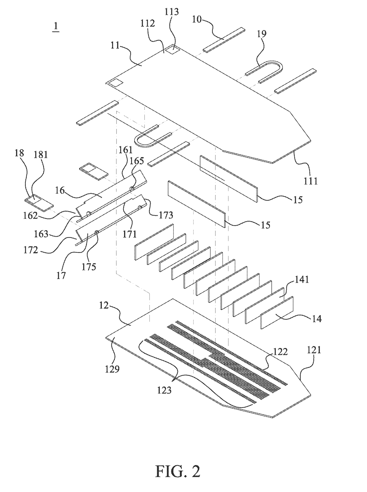
[0036]Please refer to FIG. 1. The inflatable stretcher according to a preferred embodiment of the present invention is generally denoted by reference numeral 1 and is formed of an upper cover member 11 and a lower cover member 12 that are connected together to define an outer configuration of the inflatable stretcher 1. The upper cover member 11 has a lengthwise-extended upper peripheral edge 111, and the lower cover member 12 has a lengthwise-extended lower peripheral edge 121. The upper and the lower cover member 11, 12 are fixedly connected together along the upper and the lower peripheral edge 111, 121 to form a bed-like support surface for a patient to lie flat thereon. It is noted the upper and the lower cover member 11, 12 respectively have two front corners that are beveled, so that the inflatable stretcher 1 has a tapered front end that is ...


PUM


Abstract

An inflatable stretcher includes an upper and a lower cover member connected along their outer peripheral edges to define an internal air space. The lower cover member has a plurality of perforations forming an overall pattern contoured to the shape of a human body. First and second partitioning member are disposed in the air space and connected to the upper and lower cover members to divide the air space into a plurality of widthwise-extended air release passages and two lengthwise-extended air flow passages located at two lateral sides of the air release passages. A flow opening is formed between each second partitioning member and each corresponding first partitioning member. The flow openings respectively have a cross-sectional area smaller than that of each air release passage, enabling air supplied from an inflation device into the air space to produce an increased air lifting force at positions corresponding to a patient's hips.

Description

FIELD OF THE INVENTION[0001]The present invention relates to an inflatable stretcher for carrying a patient thereon, and more particularly to an inflatable stretcher that can be quickly inflated and enables operators to conveniently transfer the patient lying thereon to another support surface.BACKGROUND OF THE INVENTION[0002]In the past, it is relatively difficult to manually move an immovable patient, such as an injured person in an accident, an aged person or other disabled persons, onto a bed or a stretcher that provides a support surface, and at least two or three nursing personnel are needed to laboriously complete this work. To solve this problem, an inflatable stretcher has been developed and introduced into the market to enable easy transport of an immovable patient with fewer operators.[0003]The conventional inflatable stretcher usually has a plurality of perforations formed on a bottom surface thereof. When using the conventional inflatable stretcher, first position the i...

Claims


Application Information

Patent Timeline
Patent Type & Authority Applications(United States)
IPC IPC(8): A61G7/10A61G1/013A61G1/048A61G1/044
CPCA61G7/1021A61G1/044A61G1/048A61G1/013A61G1/01A61G7/1028
Inventor LIU, OSCAR
Owner CAREMED SUPPLY
Learn More