Method and apparatus for the two-stage grinding of fresh stock
Inactive Publication Date: 2018-07-26
KHD HUMBOLDT WEDAG GMBH
0 Cites 3 Cited by
AI-Extracted Technical Summary
Problems solved by technology
This usually leads to a high cycle count of the stock, this being disadvantageous in terms of economy as well as process technology.
A particular challenge in terms of process technology lies in mutually adapting the operation of the two roller presses.
Alternatively, an enlargement of the second roller press and/or the operating parameters of the latter would have to be performed, this being disadvantageous in terms of the expenditure in energy and costs.
On the other hand, because of the bypass part-flow that bypasses the second roller press, the division of the flow of ground dock from the first roll...
Method used
[0023]According to the invention, the rougher ground stock of the first part-flow 12 is supplied to a second roller press 14 and in the roller gap 15 of the latter is comminuted to re-ground stock 16. The first roller press 4 is advantageously disposed vertically above the second roller press 14 or else above the latter but so as to be laterally offset such that the transportation of the ground stock of the first part-flow 12 is performed in an economically favorable manner by gravity. In principle however, transportation by means of a transportation device is also possible. The re-ground stock 16 in the exemplary embodiment illustrated is conveyed onward by means of a transportation belt 17, that is to say, in particular, transported to the classifiers of a recirculating grinding plant (and herein is optionally first fed into a pneumatic conveyor). Furtherm...
Benefits of technology
[0013]In a further design embodiment of the invention it is furthermore provided that the stock feeding device of the second roller press, in particular for reasons of safety, has an overflow for discharging excess fed stock. It is avoided on account thereof that unforeseen variations in the feeding of stock, that arise rapidly, lead t...
Abstract
A method and apparatus for grinding fresh stock, comprising comminuting the fresh stock in a first roller press roller gap into ground grinding stock, dividing the ground grinding stock via an adjustable divider into a first and second part stream in a variably adjustable ratio and comminuting the ground grinding stock of the first part stream in a second roller press. The adjustable divider divides ground grinding stock into an intermediate stream comprising ground grinding stock issuing from an intermediate roller gap region, and into two peripheral streams each comprising ground grinding stock issuing from one of the two roller gap peripheral regions. The two peripheral streams are combined to form the first part stream and the intermediate stream forms the second part stream. The second part stream is conveyed from the divider into a bypass line, passing the second roller press.
Application Domain
Grain treatments
Technology Topic
Engineering
Image
Examples
- Experimental program(1)
Example
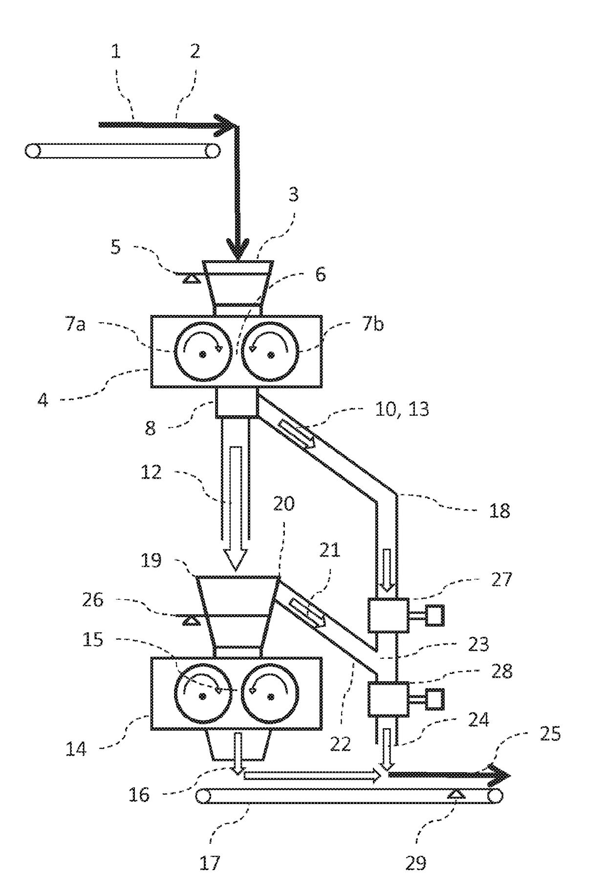
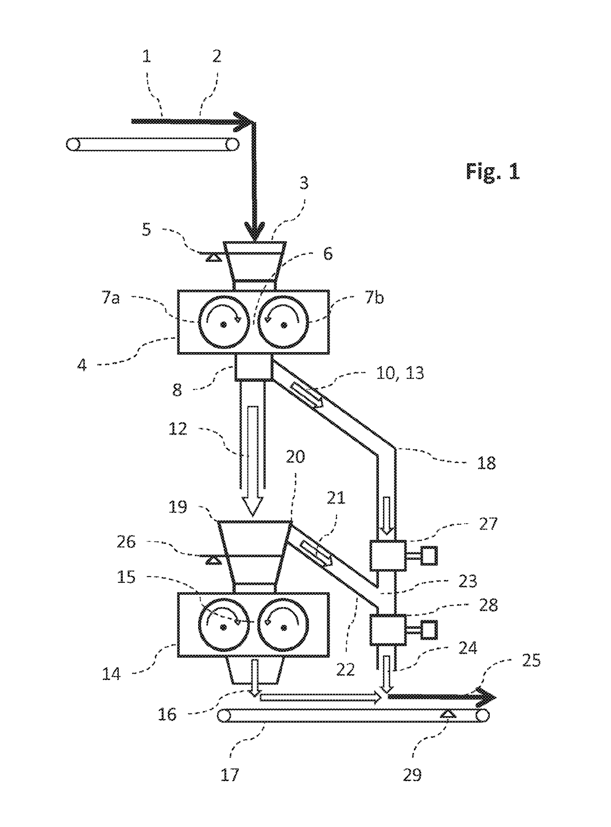
[0022]An exemplary embodiment of the method according to the invention for grinding granular, brittle fresh stock 1 by way of a corresponding device according to the invention is schematically illustrated in FIG. 1. Fresh stock 1, optionally conjointly with the stock 2 that has been recirculated in a recirculating grinding plant (not completely illustrated), is fed into the stock feeding device 3 of the first roller press 4. In order for the fed quantity to be metered in a suitable manner, the filling level 5 in the stock feeding device 3 is controlled and is regulated in a regulator circuit having the mass flow of the fresh stock 1 to be fed as an actuating variable. The fresh stock 1 (conjointly with recirculated stock 2) is comminuted to ground stock under high pressure in the roller gap 6 between the rollers 7a, 7b of the first roller press 4 and herein is crushed to form flakes. A separator installation 8 is disposed directly below the entire roller gap 6 in the longitudinal extension thereof. The ground stock that in the normal case continuously exits downward from the roller gap 6 over the entire length thereof is combined by means of adjustable separation means 9 (FIG. 2) that are disposed in the separator installation 8, the ground stock herein being divided into a central flow 10 of ground stock and into two peripheral flows 11a, 11b of ground stock. The normal case of stock being fed by means of the stock feeding device 3 in a central manner (when viewed in the longitudinal extent) above the roller gap 6 is assumed here. By virtue of the distribution of pressure along the roller gap 6, the central flow 10 is composed of more intensely comminuted material, i.e., material that on average is more finely granulated, than the two peripheral flows 11a, 11b. The two peripheral flows 11a, 11b are combined to form a first part-flow 12 of ground stock; the central flow 10 forms a second part-flow 13. The mutual mass-flow ratio of the two part-flows 12, 13 is determined by the separator installation 8 (by way of the position of the separation means 9).
[0023]According to the invention, the rougher ground stock of the first part-flow 12 is supplied to a second roller press 14 and in the roller gap 15 of the latter is comminuted to re-ground stock 16. The first roller press 4 is advantageously disposed vertically above the second roller press 14 or else above the latter but so as to be laterally offset such that the transportation of the ground stock of the first part-flow 12 is performed in an economically favorable manner by gravity. In principle however, transportation by means of a transportation device is also possible. The re-ground stock 16 in the exemplary embodiment illustrated is conveyed onward by means of a transportation belt 17, that is to say, in particular, transported to the classifiers of a recirculating grinding plant (and herein is optionally first fed into a pneumatic conveyor). Furthermore, according to the invention, the more finely granulated ground stock of the second part-flow 13 is not guided to the second roller press 14, but past the latter in a bypass line 18. The second roller press 14 on account thereof can operate at a lower throughput than the first roller press 4 such that a suitable tuning of the operating parameter (in particular of the revolutions) of the two roller presses 4, 14 is achievable without having to reduce the output of the first roller press 4. The division into the part-flows 12 and 13 with the different grain-size distributions thereof has the advantage that the bypass is formed by the more finely granulated ground stock proportion. This within a recirculating grinding plant reduces the number of recirculation cycles of non-classified material and overall increases the fine granularity in the finished product.
[0024]The second roller press 14 likewise has a stock feeding device 19. For reasons of safety in terms of unforeseeable, rapid variations in the mass flow of the first part-flow 12 that are, as such, difficult to avoid, an overflow 20, by way of which excess fed stock 21 is guided through a connection line 22 into the bypass line 18 at the introduction point 23, is provided. The material flow 24 that is composed of the excess fed stock 21 that is optionally present and of the second part-flow of ground stock is released in the exemplary embodiment illustrated onto the transportation belt 17 where the material flow 24 conjointly with the re-ground stock 16 forms the total mass flow 25, i.e., the sum of the mass flows of the first part-flow 12 and of the second part-flow 13.
[0025]The operation of the two sequentially disposed roller presses 4, 14 can be mutually tuned in an optimal manner when the filling level in the stock feeding device 19 into which the first part-flow 12 is fed is regulated as the process variable in a regulator circuit. The actuated position of the separation means 9 in the separator installation 8 is used as the actuating variable in the regulator circuit, that is to say, that a controlled modification of the proportional division of the first part-flow 12 and the second part-flow 13, or of the percentagewise proportion of the total mass flow 25 made up by the bypass-type second part-flow 13 is brought about.
[0026]Apart from a continually performed measurement of the filling level 26 in the stock feeding device 19 of the second roller press 14, the following is provided for carrying out the regulation: a first device 27 for measuring the mass flow of the second part-flow 13 of ground stock in the bypass line 18 between the separator installation 8 and the introduction point 23; and (/or) a second device 28 for measuring the mass flow of the material flow 24 that is composed of the second part-flow 13 and of the excess fed stock after the introduction point 23; and a third device 29 for measuring the mass flow of the total mass flow 25, the latter in the exemplary embodiment illustrated being provided as a belt balance 29. The regulator circuit for the filling level 26 in the stock feeding device 19 of the second roller press 14 can be operated under parameters set for the actuation range of the actuating variable (the position of the separation means 9) with the aid of the measuring values that are acquired continuously or at regular discrete temporal intervals. For example, for the operation within a typical recirculating grinding plant for producing cement, a proportion of the total mass flow 25 made up by the mass flow of the second part-flow 13 that is diverted as a bypass of at least 10% and at most 40%, preferably at least 15% and at most 30% proves to be advantageous for a sufficiently fine grain-size distribution in the finished product, for a suitable mutual tuning of the roller presses 4, 14, and for an economically favorable low number of cycles in the circuit.
[0027]The supply of the fresh stock 1, optionally conjointly with stock 2 that is recirculated in a grinding circuit, to the stock feeding device 3 of the first roller press 4 is illustrated in a schematic lateral illustration at the top of FIG. 2. Because of the lateral perspective, only one roller 7a of the first roller press 4 can be seen. The stock 1, 2 that is fed in a central manner typically forms a flattened bulk cone 30 above the roller gap 6 (obscured in the illustration) having the greatest height in the center and decreasing in height towards the peripheries, in each case, in relation to the longitudinal extent of the rollers 7a, 7b, or of the roller gap 6, respectively. The separator installation 8 (not illustrated in its entirety) having the separation means 9 is disposed directly below the roller gap. The division in the exemplary embodiment illustrated is performed mechanically by adjustable flaps 31. The flaps 31 that are located in the housing of the separator installation 8 that extends below the entire roller gap 6 are disposed so as to be mirror-symmetrical to the center of the longitudinal extent of the roller gap and so as to be movable, for example by way of a motor. The flaps 9, 31 can be displaceable in opposite mutual directions below the roller gap 6 or, as in the exemplary embodiment illustrated, pivotable in the angular position thereof (in mutually opposite directions) about a rotation axis.
[0028]On account of the respective defined position of the separation means 9, 31 in which, in a purely geometrical manner, a central roller gap region 32 (marked in a symbolic manner) is delimited along the roller gap 6 from, in each case, one peripheral roller gap region 33a, 33b that is located to the left and to the right (in the illustration) thereof by way of the (free) ends of the flaps 9, a division of the ground stock that exits in a downward manner from the entire roller gap 6 into a central flow 10 of finer ground stock and into, in each case, one peripheral flow 11a, 11b of rougher ground stock takes place. As has been described in the context of FIG. 1, the central flow 10 as a second part-flow 13 is furthermore directed as a bypass around the second roller press 14 while the peripheral flows 11a, 11b conjointly form the first part-flow 12 which for re-grinding is fed into the second roller press 14.
[0029]In the case of a potential other distribution of pressure, or of the degree of comminution, respectively, along a roller gap 6, a corresponding advantageous division into part-flows having mutually dissimilar particle-size distributions of particle sizes can be performed by a person skilled in the art by way of a correspondingly adapted separator installation 8.
[0030]As is apparent from the foregoing specification, the invention is susceptible of being embodied with various alterations and modifications which may differ particularly from those that have been described in the preceding specification and description. It should be understood that I wish to embody within the scope of the patent warranted hereon all such modifications as reasonably and properly come within the scope of my contribution to the art.
LIST OF REFERENCE SIGNS
[0031] 1 Fresh stock [0032] 2 Recirculated stock [0033] 3 Stock feeding device (first roller press) [0034] 4 Roller press (first) [0035] 5 Filling level (first roller press) [0036] 6 Roller gap (first roller press) [0037] 7a, 7b Roller (first roller press) [0038] 8 Separator installation [0039] 9 Separation means [0040] 10 Central flow [0041] 11a, 11b Peripheral flow [0042] 12 First part-flow [0043] 13 Second part-flow [0044] 14 Roller press (second) [0045] 15 Roller gap (second roller press) [0046] 16 Re-ground stock [0047] 17 Transportation belt [0048] 18 Bypass line [0049] 19 Stock feeding device (second roller press) [0050] 20 Overflow [0051] 21 Excess fed stock [0052] 22 Connection line [0053] 23 Introduction point [0054] 24 Material flow [0055] 25 Mass flow (total) [0056] 26 Filling level (second roller press) [0057] 27 Mass flow measuring device (first) [0058] 28 Mass flow measuring device (second) [0059] 29 Mass flow measuring device (third) [0060] 30 Bulk cone [0061] 31 Flap [0062] 32 Central roller gap region [0063] 33a, 33b Peripheral roller gap region
PUM


Description & Claims & Application Information
We can also present the details of the Description, Claims and Application information to help users get a comprehensive understanding of the technical details of the patent, such as background art, summary of invention, brief description of drawings, description of embodiments, and other original content. On the other hand, users can also determine the specific scope of protection of the technology through the list of claims; as well as understand the changes in the life cycle of the technology with the presentation of the patent timeline. Login to view more.