Batch centrifuge filter screen

a filter screen and batch centrifuge technology, applied in the field of batch centrifuges, can solve the problems of reducing the efficiency of batch centrifuges

Active Publication Date: 2018-07-26
AQSEPTENCE GROUP INC
View PDF6 Cites 6 Cited by
  • Summary
  • Abstract
  • Description
  • Claims
  • Application Information

AI Technical Summary

Problems solved by technology

Filter screens of batch centrifuges typically experience a significant amount of wear during operation, such as may result from engagement with abrasive sugar crystals and from engagement with scraper arms.
However, because they are so thin, such foils and meshes lack durability and must be replaced more often than is desirable.
In addition, due to the relatively fragile construction of such foils and meshes, heavy cylindrical mesh backings are typically between the filter screen and the centrifuge wall to provide thin filter screens with additional support.
Such mesh backings, however, add weight and cost and the additional weight may impede the functioning if the centrifuge.
Although use of filter screens formed of thicker, more durable foils and meshes may be advantageous, they have not been used in centrifuge applications because, due to their rigidity, they cannot be collapsed to fit through the opening in the top of the centrifuge.
Furthermore, any blockage or damage caused during operation would require the entire foil to be replaced, adding cost and time consumption.

Method used


Image

  • Batch centrifuge filter screen
  • Batch centrifuge filter screen
  • Batch centrifuge filter screen

Examples


first embodiment

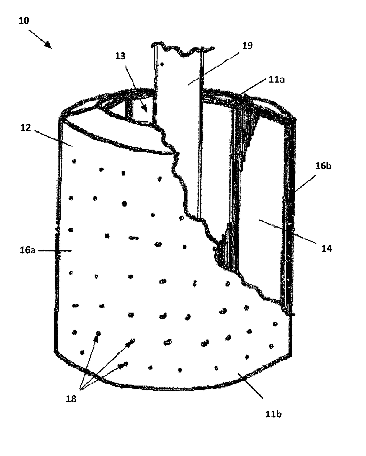
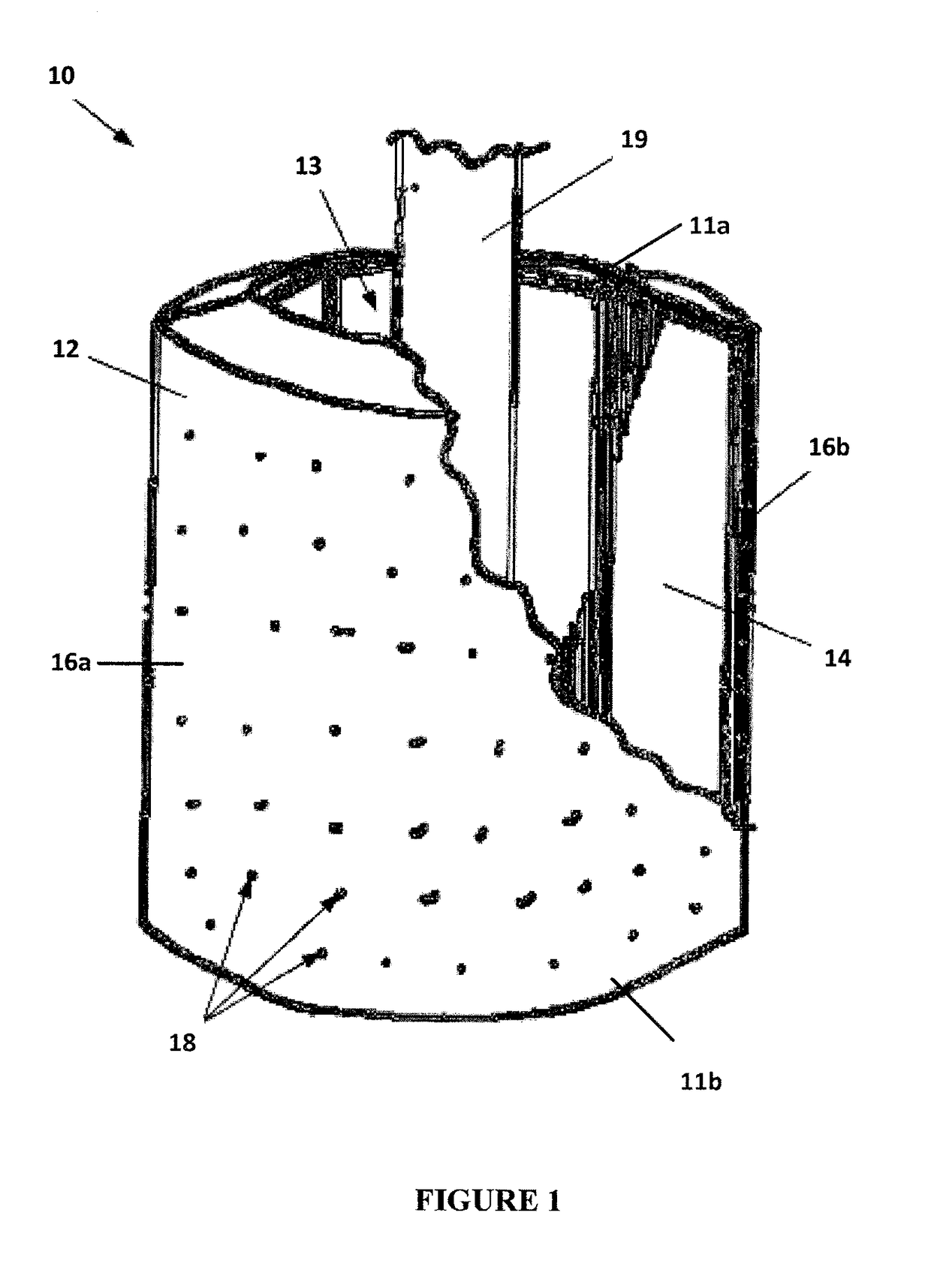
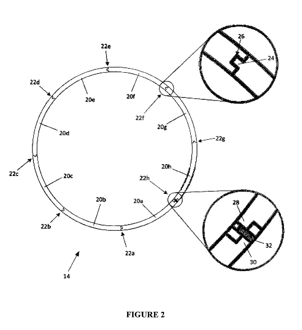
[0046]As best shown in the top view of the filter screen 14, in the invention, illustrated in FIG. 2, the filter screen 14 may be formed of a plurality of curved screen panels 20a-h that are joined together at their lateral sides to form the assembled cylindrical filter screen 14. In some embodiments each of the panels 20a-h may cover at least a portion of the basket 12 and may be shaped substantially similar to the curvature of the basket 12. In some embodiments at least one of the curved screen panels may comprise one or more sub-panels (not shown) arranged to form a filter screen with a grid like structure. In this regard, the sub-panels associated with one screen panel may be arranged in a parallel or a staggered manner with respect to the sub-panels of another screen panel. The optimal size and number of the curved screen panels 20 may be determined based on a number of factors comprising, the size, shape and volume of the basket 12, the dimensions of the opening 13, the rigidi...

second embodiment

[0059]Referring to FIG. 5, it is contemplated that, in the invention, instead of the tongue and groove features 24, 26 and shoulders 28, 30 described above, the opposing longitudinal edges of the frame portion 42 of the curved screen panels 20a-g may alternatively be formed with a plurality of longitudinally-spaced, complementary hook and loop features 124, 126. As depicted in FIG. 6, which illustrates a section of the top view of the assembled filter screen 14, the curved screen panel 20b comprises a hook feature 124 on the on the lateral side 42b of the frame portion 42 and a loop feature 126 on the opposite lateral side 42d of the frame portion 42 (only one hook feature 124 and one loop feature 126 are visible in the edge view shown in FIG. 6). The hook and loop features (124, 126) may be formed integrally with the frame portion 42, may be machined on the frame portion 42 or may be separate components that are fixedly fastened to the frame portion 42. The curved screen panels 20a...


PUM

PropertyMeasurementUnit
forceaaaaaaaaaa
thicknessaaaaaaaaaa
spin timeaaaaaaaaaa

Abstract

A batch centrifuge having a filter screen that can be expeditiously removed and replaced and that is more rigid and more durable than filter screens that are typically employed in current practice. The batch centrifuge may include a centrifuge basket and a cylindrical filter screen disposed within the centrifuge basket, wherein the filter screen is formed of a plurality of curved panels that fit together at adjoining edges. In some embodiments, each of the curved panels may be small enough to fit through an opening in the top of the centrifuge basket without being bent or otherwise deformed.

Description

CROSS-REFERENCE TO PRIORITY APPLICATION[0001]This application claims the benefit of U.S. Patent Application Ser. No. 62 / 037,160 for a Batch Centrifuge Filter Screen (filed Aug. 14, 2014), which is hereby incorporated by reference in its entirety.FIELD OF THE INVENTION[0002]The disclosure relates generally to the field of sugar processing equipment and more particularly to a batch centrifuge used for separating sugar crystals from massecuite.BACKGROUND[0003]Batch centrifuges are commonly employed in sugar processing for separating sugar crystals from massecuite. During such separation, an amount of massecuite is placed in a centrifuge basket. The basket is then accelerated to a predetermined angular velocity which is maintained for a predetermined spin time. As the basket spins, liquid in the massecuite is forced through a cylindrical filter screen that covers an interior sidewall of the basket while sugar crystals are retained by the filter screen. The separated liquid is flushed th...

Claims


Application Information

Patent Timeline
Patent Type & Authority Applications(United States)
IPC IPC(8): B04B7/16B04B11/04B04B7/18C13K13/00
CPCB04B7/16B04B11/04B04B7/18C13K13/007
Inventor DEHN, STEVENFLANSBURG, CHARLES
Owner AQSEPTENCE GROUP INC
Why Eureka
Try Eureka