Pocket hole jig

a technology for pocket holes and jigs, which is applied in the field of pocket hole jigs, can solve the problems of lack of accurate positioning of the pocket hole jigs

Active Publication Date: 2018-08-02
TECHTRONIC CORDLESS GP
View PDF1 Cites 13 Cited by
  • Summary
  • Abstract
  • Description
  • Claims
  • Application Information

AI Technical Summary

Benefits of technology

[0004]The present invention provides, in one aspect, a pocket hole jig for locating pocket holes in a workpiece. The pocket hole jig includes base with a base plate and first and second lateral side walls extending along the base plate, and a body disposed between the first and second lateral side walls and slidable along the base in a forward direction and a rearward direction. The body includes a drill bit aperture angled downward toward the base plate. The pocket hol

Problems solved by technology

Known pocket hole jigs lack a means for accurately positioning t

Method used


Image

  • Pocket hole jig
  • Pocket hole jig
  • Pocket hole jig

Examples


Embodiment Construction

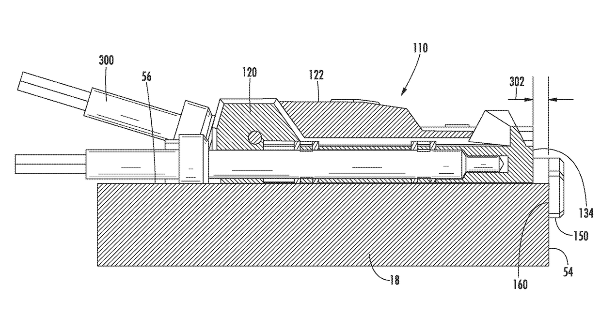
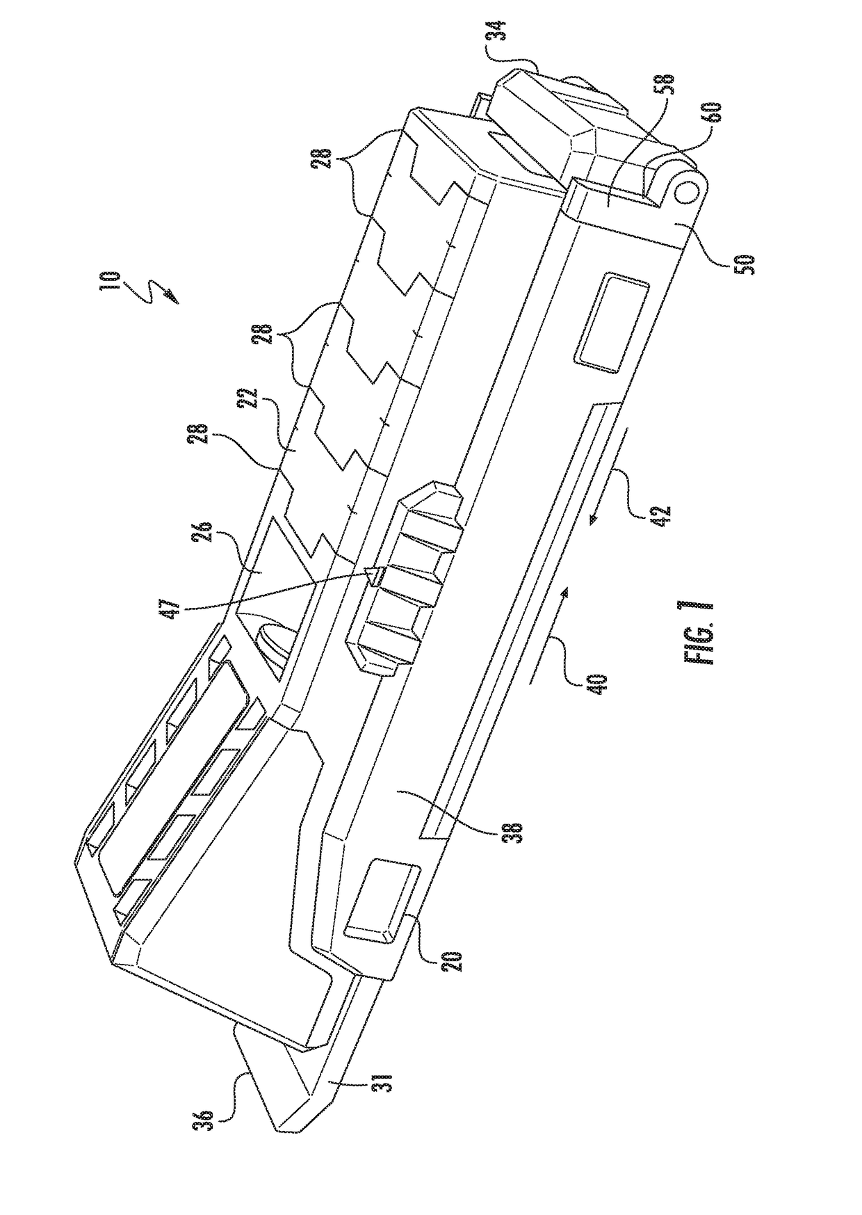
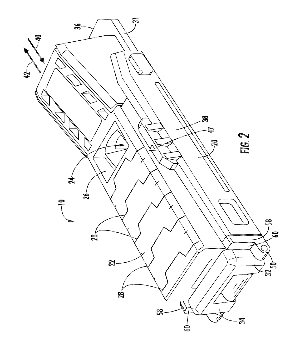
[0023]FIG. 1 is a perspective view of a pocket hole jig 10 according to one embodiment. The jig 10 can be used to properly locate and facilitate drilling pocket holes 12, 16 in a workpiece 18, such as a piece of wood (FIG. 6). The holes 12, 16 each receive a pocket screw 19 that is used to attach the workpiece 18 to a second workpiece.

[0024]Referring to FIG. 1, the jig 10 includes a base 20 and a body 22 movable relative to the base 20. The body 22 includes a drill bit aperture 24 (FIG. 3), a window 26, and indicia 28. The aperture 24 is angled downwardly toward the base 20 at an oblique angle and is shaped and sized to receive and guide a drill bit. When a drill bit is inserted through the aperture 24, the bit extends through an aperture 30 (FIG. 3) in the base 20 to drill into the workpiece 18. The window 26 is provided so that a user can see the drill bit traveling through the aperture 24 and into the workpiece and so that debris (e.g., wood chips) created by the drill bit can ex...


PUM

PropertyMeasurementUnit
Thicknessaaaaaaaaaa
Angleaaaaaaaaaa
Surfaceaaaaaaaaaa

Abstract

A pocket hole jig includes base with a base plate and first and second lateral side walls extending along the base plate, and a body disposed between the first and second lateral side walls and slidable along the base in a forward direction and a rearward direction. The body includes a drill bit aperture angled downward toward the base plate. The pocket hole jig also includes a fence movable between a raised position and a lowered position and having a contact surface engageable with an end of the workpiece when the fence is in the lowered position to position the base a predetermined distance from the end of the workpiece. The contact surface is in a first position when the fence is in the raised position and a second position when the fence is in the lowered position. The second position is forward of the first position.

Description

CROSS-REFERENCE TO RELATED APPLICATIONS[0001]This application claims priority to co-pending U.S. Provisional Patent Application No. 62 / 453,086, filed on Feb. 1, 2017, and to co-pending U.S. Provisional Patent Application No. 62 / 515,862, filed on Jun. 6, 2017, the entire contents of which are incorporated herein by reference.FIELD OF THE INVENTION[0002]The present invention relates to pocket hole jigs, and particularly to a pocket hole jig having a fence for aligning the pocket hole jig to a workpiece.BACKGROUND OF THE INVENTION[0003]Pocket hole jigs are commonly used to facilitate locating and drilling pocket holes in a workpiece. Known pocket hole jigs lack a means for accurately positioning the jig with respect to either of an end or a face of a workpiece.SUMMARY OF THE INVENTION[0004]The present invention provides, in one aspect, a pocket hole jig for locating pocket holes in a workpiece. The pocket hole jig includes base with a base plate and first and second lateral side walls ...

Claims


Application Information

Patent Timeline
IPC IPC(8): B23B39/06B23B47/28B23B49/04
CPCB23B39/06B23B47/287B23B49/04B23B2247/10B23B2247/12B23B2260/0487B23B47/28
Inventor EVATT, THOMASTHACKERY, CLINTON C.KEITH, JAMES
Owner TECHTRONIC CORDLESS GP
Why Eureka
Try Eureka