Filling device

Inactive Publication Date: 2018-08-09
TOYO SEIKAN KAISHA LTD
View PDF6 Cites 0 Cited by
  • Summary
  • Abstract
  • Description
  • Claims
  • Application Information

AI Technical Summary

Benefits of technology

This patent describes a new filling nozzle design for containers that prevents ink from splashing or creating peaks on the surface of the ink. The design uses a gas ejection hole in the nozzle and plunger, which allows for a continuous flow of gas between them, reducing the likelihood of peaks. The design also includes a gap between the nozzle and plunger that can be used as a gas ejection hole, simplifying the device and improving its design. Additionally, the design can be easily replaced with different nozzle tools for different contents and containers, further improving its flexibility. The design also includes a gap between the nozzle and plunger that is maintained with a suitable width, ensuring even gas ejection. Overall, the design reduces processing load, improves efficiency, and reduces likelihood of peaks on the ink surface.

Problems solved by technology

The problem is that, when the container C is sealed with a lid with such a pointed peak formed on the upper surface of the contents, the pointed peak is flattened by and adhered on the back surface of the lid, which will compromise the aesthetic appearance when the container is opened.
Another problem is that the contents may adhere on a container flange part C1 as a result of the peak being flattened by the lid, and may cause a defect in the seal by the lid.

Method used


Image

  • Filling device
  • Filling device
  • Filling device

Examples


Embodiment Construction

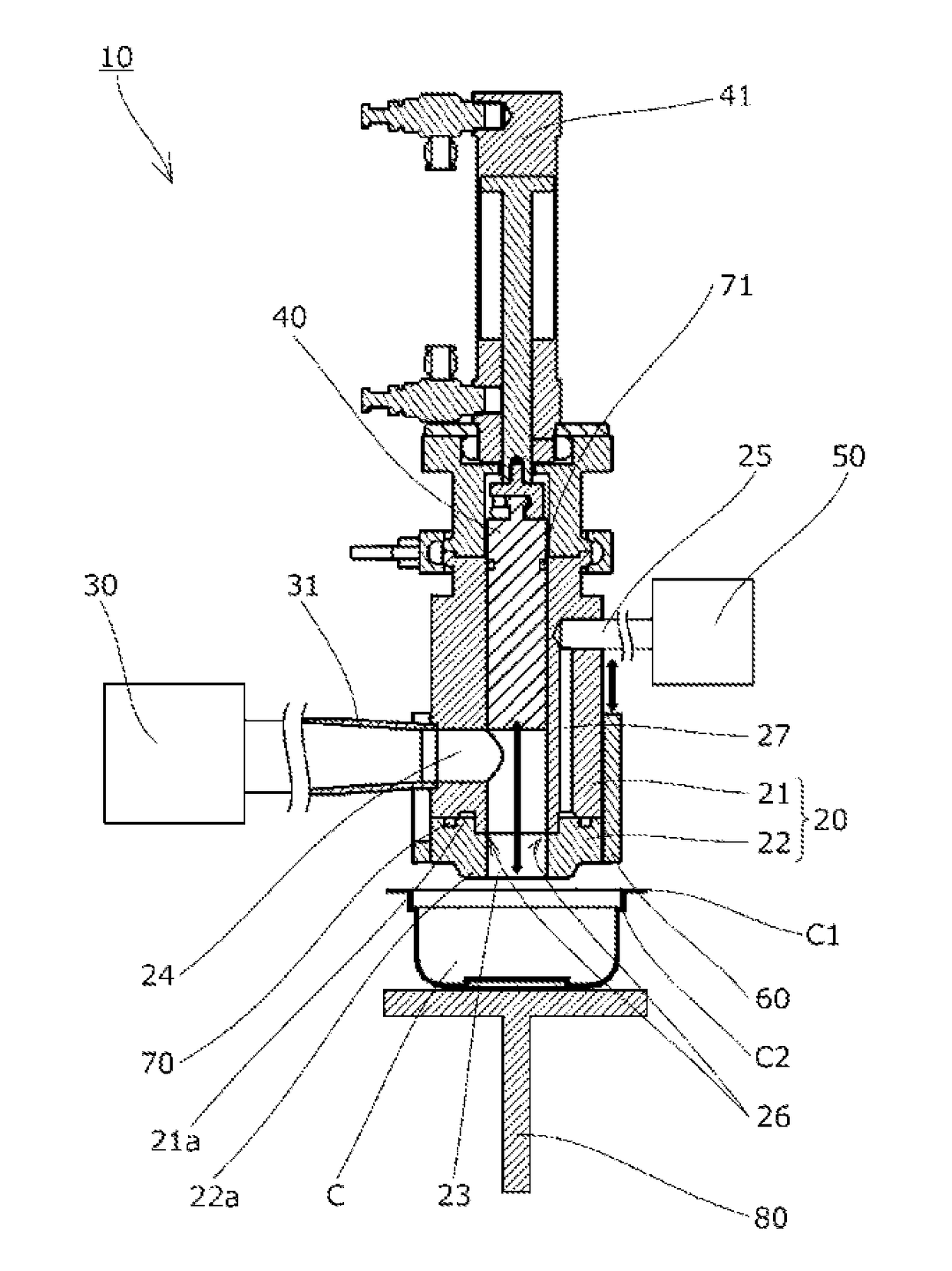
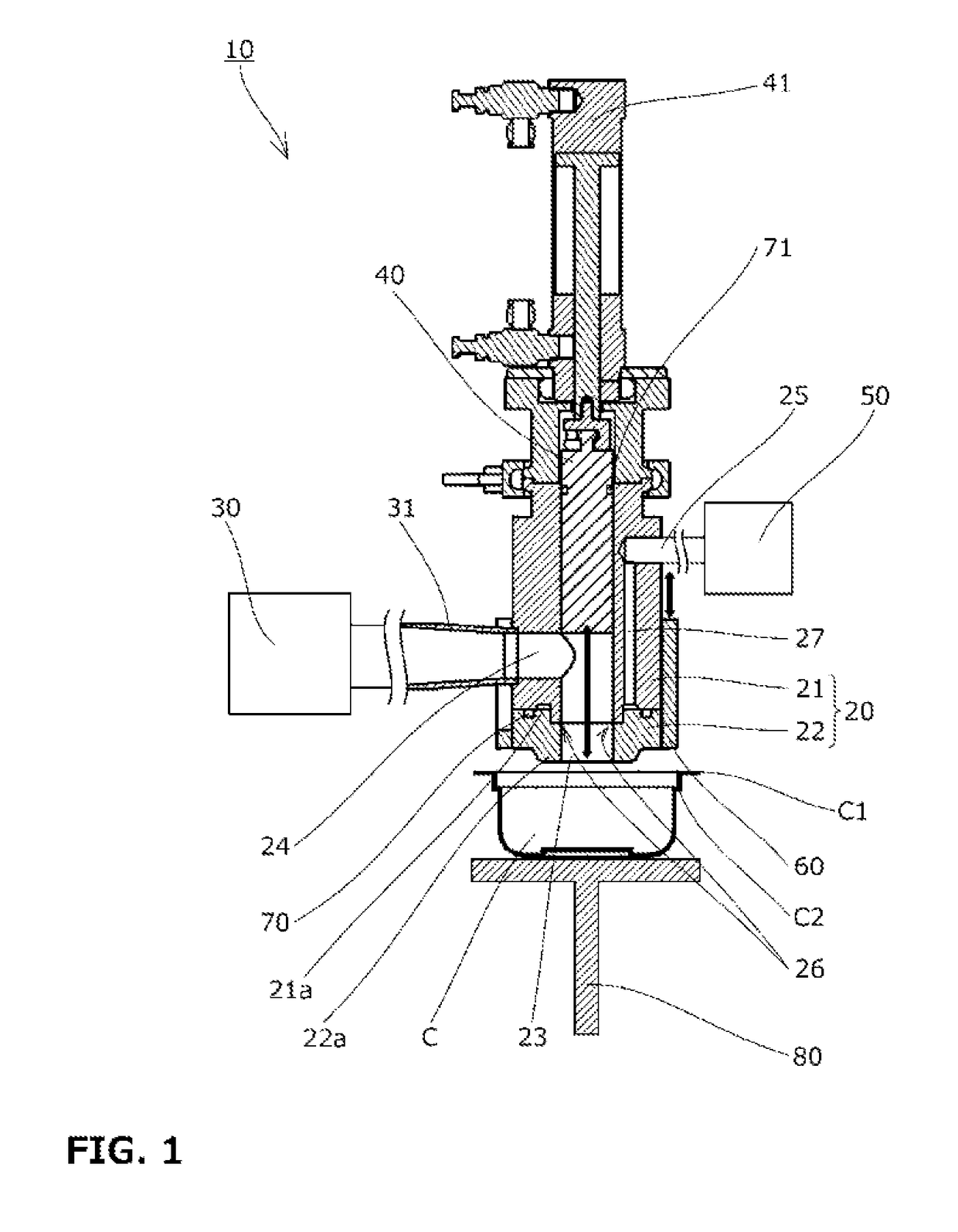
[0053]Below, the filling device 10 according to one embodiment of the present invention will be described with reference to the drawings.

[0054]The filling device 10 fills a container C with viscous contents B such as a meat product. As shown in FIG. 1, the device includes a filling nozzle 20 having a nozzle hole 23, a contents supplier 30 that supplies the contents B to the nozzle hole 23, a plunger 40 that is disposed inside the nozzle hole 23 such as to be movable up and down and pushes out the contents B supplied to the nozzle hole 23 downward, a gas supplier 50 that supplies a gas A, a nozzle cover 60 placed around the filling nozzle 20, first and second packings 70 and 71 in an annular form that seal respective parts, and a container lifter 80 that moves the container C up and down.

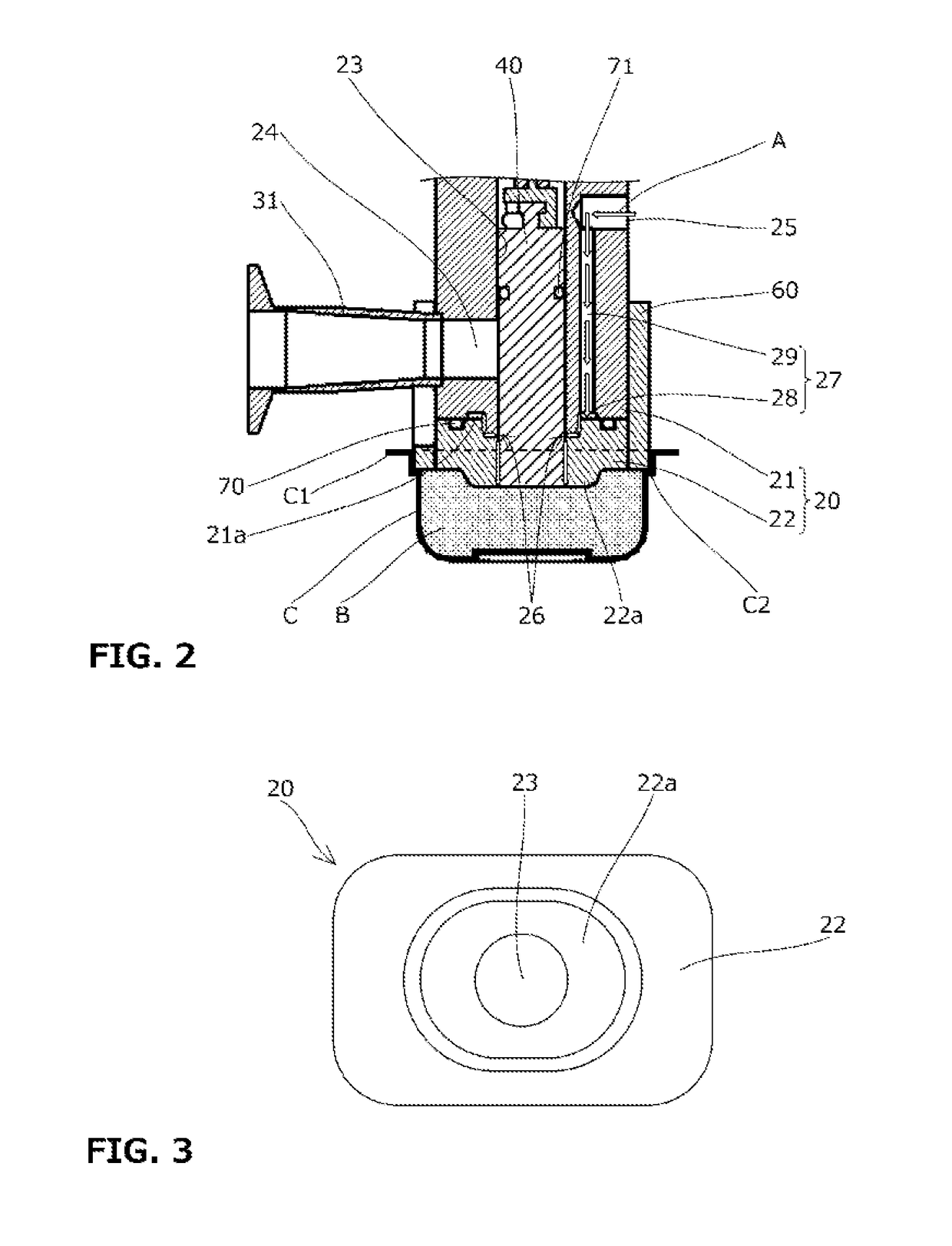
[0055]The constituent elements of the filling device 10 will each be described below with reference to FIG. 1 to FIG. 3.

[0056]First, the filling nozzle 20 includes a cylindrical nozzle hole 23 that e...


PUM


Abstract

To provide a filling device that realizes simplification of device configuration, improvement of design freedom, and redaction of production loads, and that prevents formation of a pointed peak on the upper surface of packed contents, or uneven filling of the container. Provided is a filling device (10) including a filling nozzle (20), a contents supplier (30), a plunger (40), and a gas supplier (50). A gas inlet (25) connected to the gas supplier (50), a gas outlet (26) opened to the nozzle hole (23), and a gas flow passage (27) are formed in the filling nozzle (20). The gas (A) supplied from the gas supplier (50) is ejected from a gap between an inner circumferential surface of the nozzle hole (23) and an outer circumferential surface of the plunger (40) at a lower end of the filling nozzle (20).

Description

TECHNICAL FIELD[0001]The present invention relates to a filling device for filling containers with contents, and more particularly to a filling device for filling containers with viscous contents.BACKGROUND ART[0002]As filling devices that fill containers with viscous contents such as meat products, a filling device 110 has hitherto been known which includes a filling nozzle 120 having a nozzle hole 123 formed along an up and down direction and opened downward, a contents supplier 130 that supplies contents to the nozzle hole 123, and a plunger 140 disposed inside the nozzle hole 123 such as to be movable up and down, as shown in FIG. 4 (see, for example, Patent Literature 1).[0003]In this filling device 110, the contents supplier 130 supplies a constant amount of contents to the nozzle hole 123, and the plunger 140 pushes out the contents inside the nozzle hole 123 downward, to fill a container C with the contents.[0004]In such a filling device 110, immediately after the container ...

Claims


Application Information

Patent Timeline
IPC IPC(8): B65B39/00B65B3/04
CPCB65B39/005B65B3/04B65B39/04B65B3/12B65B3/32B65B39/00
Inventor ATSUGI, MASASHIMORITA, YOSHIYUKISAWADA, MAKOTO
Owner TOYO SEIKAN KAISHA LTD
Why Eureka
Try Eureka