Light source device and projection device including the light source device
- Summary
- Abstract
- Description
- Claims
- Application Information
AI Technical Summary
Benefits of technology
Problems solved by technology
Method used
Image

Examples
first embodiment
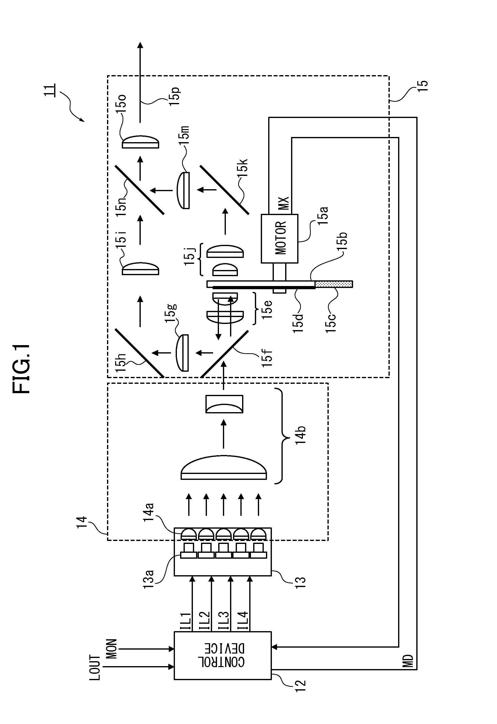
[0040]FIG. 1 is a block diagram illustrating the configuration of a light source device according to a first embodiment of the present invention.
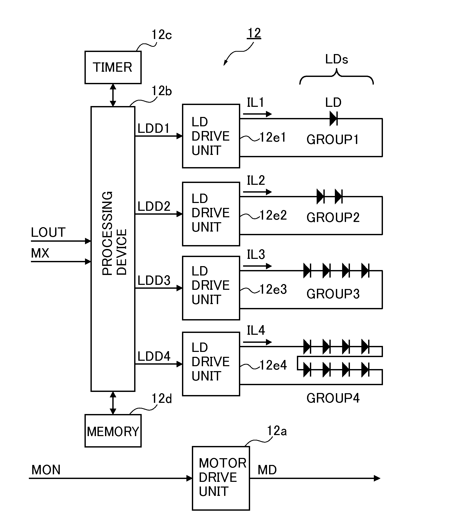
[0041]A light source device 11 includes a control device 12, an LD module 13, a first optical system 14, and a second optical system 15.
[0042]The control device 12 outputs LD-drive current IL1 to IL4 in synchronization with an incoming control signal LOUT and an index signal MX from a motor 15a. The control device 12 starts the driving of the motor 15a by outputting a motor-driving signal MD in response to an incoming control signal MON.
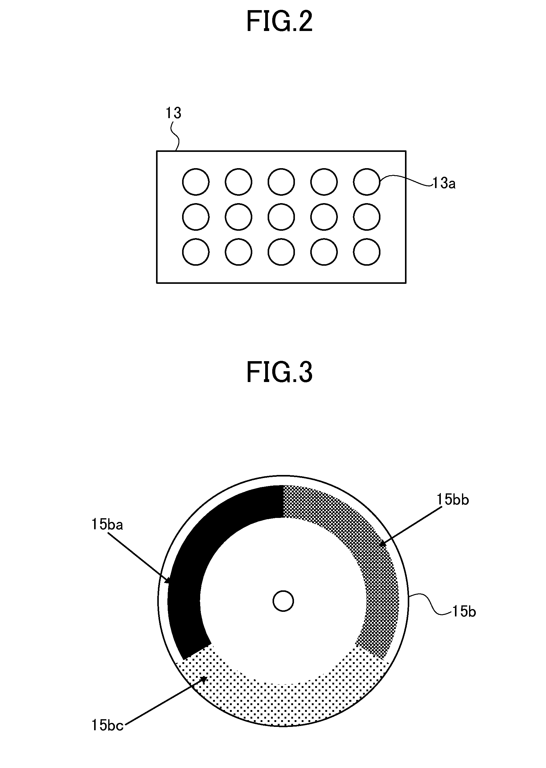
[0043]The motor 15a outputs the index signal MX synchronized with a rotation of the wheel 15b attached to a rotating shaft, simultaneously with rotating the wheel.
[0044]Specifically, in FIG. 1, the control device 12 to control the light source starts driving of the motor 15a by outputting the motor-driving signal MD when a control signal MON is affirmed (e.g. being a level “H”).
[0045]The motor 15a outputs th...
second embodiment
[0082]FIG. 11 is a schematic view of a configuration of a light source device according to a second embodiment of the present invention wherein the same reference numbers are attached to similar parts to the first embodiment shown in FIG. 1 and descriptions thereof are omitted. Further, FIG. 12 illustrates an example of the configuration of the control unit shown in FIG. 11 wherein the same reference numbers are attached to similar parts to the first embodiment shown in FIG. 4 and descriptions thereof are omitted.
[0083]First, the light source device in FIG. 11 is configured as follows: a partially-reflecting mirror 21 is installed after the collecting lens system 15o and the part of the emitted source light 15p is reflected by a partially-reflecting mirror 21 and led to the PMD (Power Monitor Device) 22. Then, a part of source light led to PMD 22 is outputted with conversion into an analog electrical signal PMO_A and entered to the control device 12 with conversion into a digital li...
third embodiment
[0089]FIG. 13 illustrates a schematic configuration of the projector according to the third embodiment of the present invention.
[0090]As shown in FIG. 13, the projector 30 includes an image control unit 31, the light source device 11, a DMD (Digital Micromirror Device) 32, an illumination optical system 33, a reflecting mirror 35, and a projection optical system 36.
[0091]In FIG. 13, the light source device 11 is the light source device shown in FIG. 1 or FIG. 11, and emits light in the red, green, and blue wavelength bands sequentially on a time-division basis.
[0092]In addition to the configuration above, at least one other light source device (not shown) can be used along with the light source device 11.
[0093]Once the image control unit 31 receives an external video signal VIN, it rotates the wheel 15b by driving the motor 15a in the light source device 11 by making the control signal MON to “H” from a frame frequency of the signal. Then, once it is detected that the motor drive un...
PUM
 Abstract
Description
Claims
Application Information
 - R&D Engineer
- R&D Manager
- IP Professional
- Industry Leading Data Capabilities
- Powerful AI technology
- Patent DNA Extraction
Browse by: Latest US Patents, China's latest patents, Technical Efficacy Thesaurus, Application Domain, Technology Topic.
© 2024 PatSnap. All rights reserved.Legal|Privacy policy|Modern Slavery Act Transparency Statement|Sitemap