Dividerless pll architecture

Active Publication Date: 2009-01-15
SILICON LAB INC
View PDF15 Cites 72 Cited by
  • Summary
  • Abstract
  • Description
  • Claims
  • Application Information

AI Technical Summary

Benefits of technology

[0006]Accordingly, a new PLL architecture is provided for implementing fractional-N (and integer) PLLs that can provide high performance, low power, and be implemented with low complexity. In an embodiment, the PLL achieves initial lock using a course fractional-N (or integer) divider driving a binary phase detector. Once frequency lock is achieved, this divider may be turned off, while the adaptive phase detector takes over control of the system front end. The fractional-N (or integer) divide circuitry may be maintained

Problems solved by technology

One aspect of PLLs is that the feedback divider tends to consume significant power

Method used


Image

  • Dividerless pll architecture
  • Dividerless pll architecture
  • Dividerless pll architecture

Examples


Example

[0029]The use of the same reference symbols in different drawings indicates similar or identical items.

DESCRIPTION OF THE PREFERRED EMBODIMENT(S)

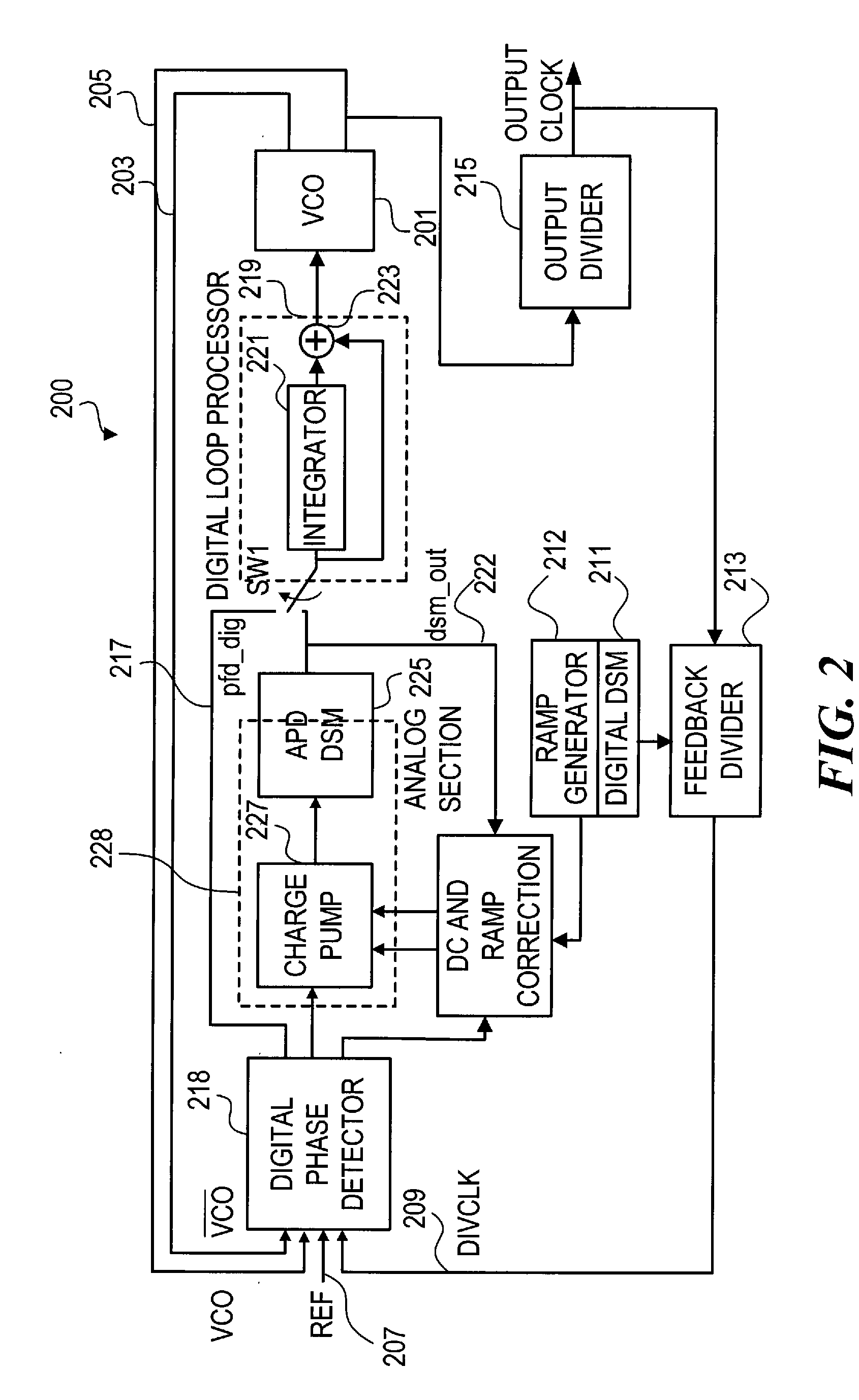
[0030]Referring to FIG. 2, illustrated is an exemplary PLL 200 according to an embodiment of the invention. The VCO 201 is assumed to yield both phases 203 and 205 of the VCO clock. These are sent to the front end for processing with the reference clock (REF clock) 207 and the output (DIVCLK) 209 of the feedback divider 213. There are two main modes of operation of PLL 200. The first is purely digital, while the PLL 200 locks to the REF clock 207. In this mode the digital delta sigma modulator (DSM) 211 generates a control signal to the Feedback Divider 213 that provides the DIVCLK 209 signal corresponding to the standard fractional-N approach, although operating on a coarse clock, i.e., lower frequency than the VCO, from the output of the Output Divider 215. A binary phase detector output (pfd_dig) 217 from the digital phase detector 218, ...


PUM


Abstract

A phase-locked loop (PLL) achieves initial lock using a course fractional-N divider driving a binary phase detector. Once frequency lock is achieved, this divider may be turned off, while an adaptive phase detector takes over control of the PLL front end. The adaptive phase detector (APD) receives input directly from the VCO and the reference clock, deriving digital control signals and a precision phase detector output. The APD operates at the update rate, generating a digital delta sigma modulator (DSM) data stream output at the update rate. The APD automatically locks to a digitally generated ramp corresponding to an expected difference between the VCO output and the reference clock, while adaptively correcting for DC errors and ramp cancellation errors.

Description

CROSS-REFERENCE TO RELATED APPLICATION(S)BACKGROUND[0001]1. Field of the Invention[0002]This invention relates to phase-locked loops (PLLs) and more particularly to PLL architectures that can provide high performance with low power utilization.[0003]2. Description of the Related Art[0004]Phase-locked loops (PLLs) are common in modern electronic systems. A high-level block diagram of a typical prior art PLL 100 is shown in FIG. 1. A phase / frequency detector (PFD) 103 compares a feedback divided signal 104 from feedback divider 105 and a reference clock signal 107. The difference is used to control the voltage controlled oscillator (VCO) 108. The PLL typically multiplies the reference clock signal using the feedback divider circuit 105. The divide value of the feedback divider 105 determines the amount of multiplication. Some PLL architectures are fractional-N PLLs where the PLL output 109 is a non-integral multiple of the reference clock 107. One aspect of PLLs is that the feedback d...

Claims


Application Information

Patent Timeline
IPC IPC(8): H03L7/00H03L7/06
CPCH03L7/0802H03L7/085H03L7/1976H03L7/0891H03L7/10H03L7/087H03L7/113
Inventor FREY, DOUGLAS R.
Owner SILICON LAB INC
Why Eureka
Try Eureka