Movable magnet for magnetically guided catheter

Active Publication Date: 2012-02-09
ST JUDE MEDICAL ATRIAL FIBRILLATION DIV
View PDF28 Cites 72 Cited by
  • Summary
  • Abstract
  • Description
  • Claims
  • Application Information

AI Technical Summary

Benefits of technology

[0007]In various embodiments, magnetic guided catheters are disclosed that prov

Problems solved by technology

Such catheter devices can be complex in their construction, and therefore are difficult to manufacture and relatively expensive to produce.
T

Method used


Image

  • Movable magnet for magnetically guided catheter
  • Movable magnet for magnetically guided catheter
  • Movable magnet for magnetically guided catheter

Examples


Example

[0020]Many specific details of certain embodiments of the invention are set forth in the following description in order to provide a thorough understanding of such embodiments. One skilled in the art, however, will understand that the present invention may have additional embodiments, or that the present invention may be practiced without several of the details described in the following description.

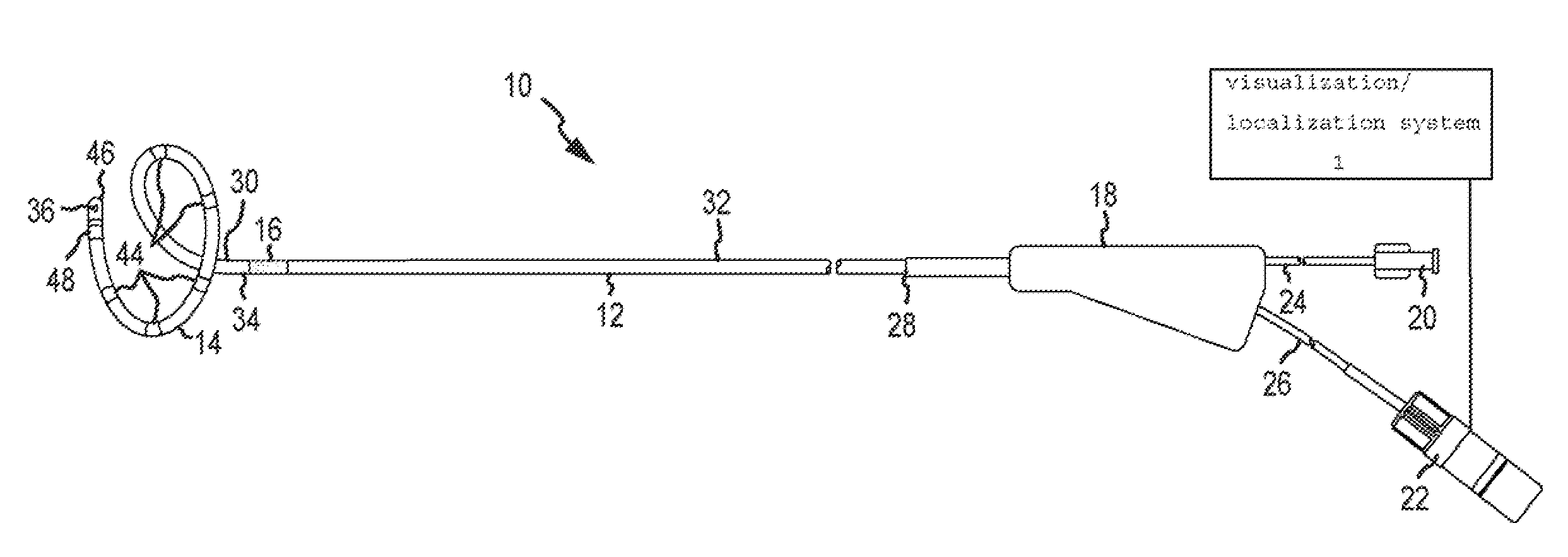
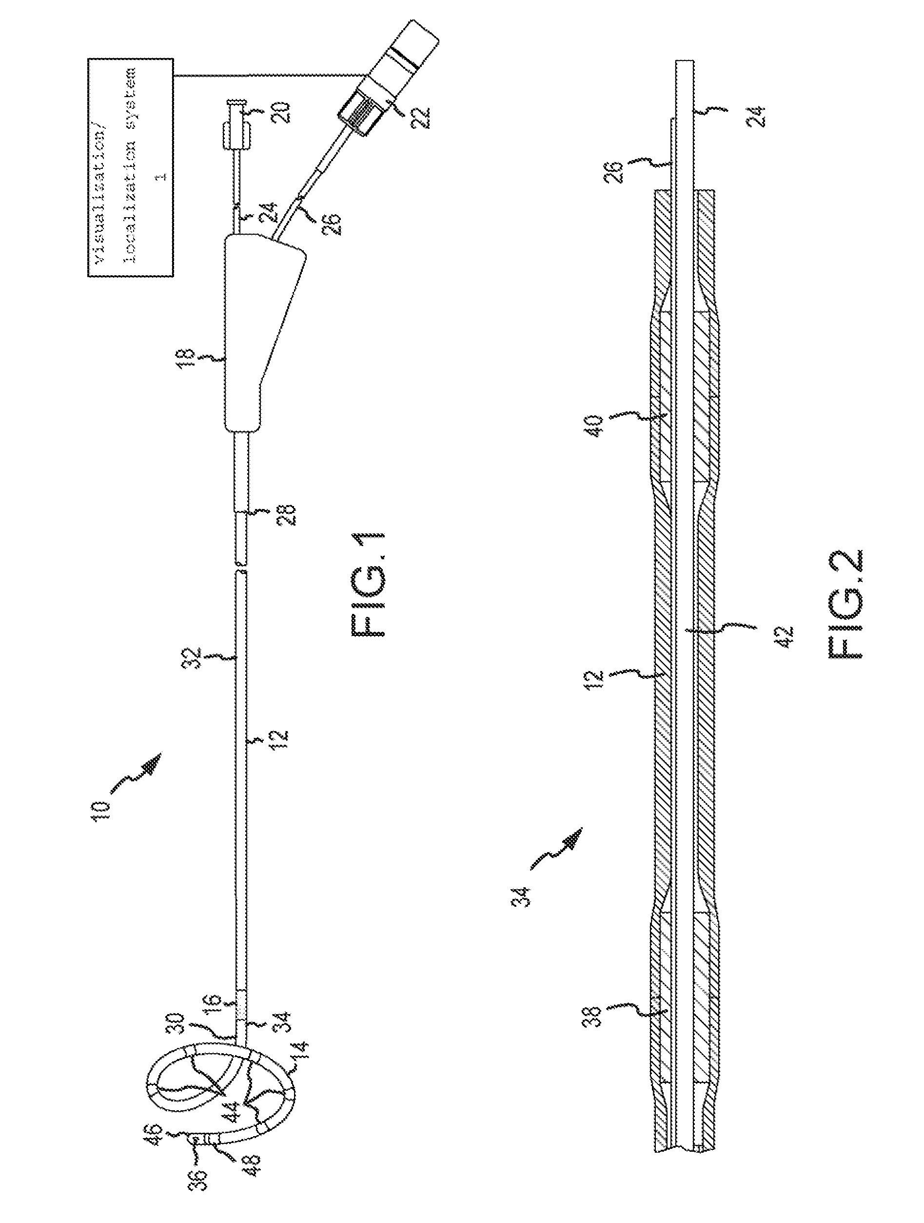
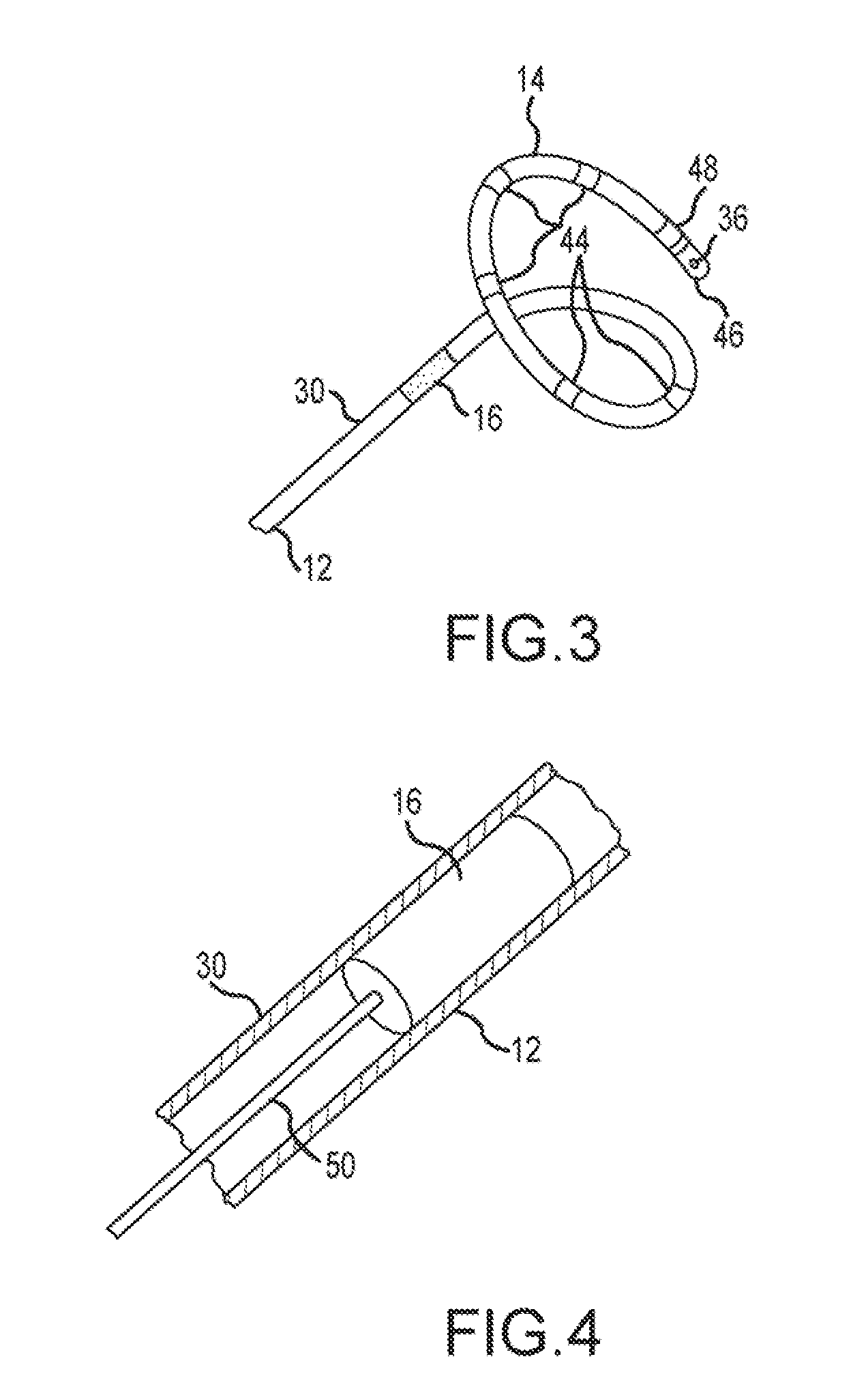
[0021]Exemplary embodiments may employ any of a wide variety of different types and configurations of catheters. In one example, the invention may be implemented as an introducer which may be positioned at the target location inside the patient's body and then used for placing of a catheter for carrying out the medical procedure. In other examples, a magnetically guided catheter may be a standard linear catheter. As will become apparent from the following description, the invention may be implemented with a single catheter, or with multiple (e.g., two or more) catheters that are utilized...


PUM


Abstract

A catheter is disclosed having a flexible tubing with a proximal end and a distal end. The catheter comprising at least one movable magnet provided within the distal end of the flexible tubing. A control mechanism is operable to selectively activate the at least one movable magnet from the proximal end of the flexible tubing. The at least one movable magnet is responsive to an external magnetic field to position and guide the distal end of the flexible tubing within a body of a patient.

Description

BACKGROUND OF THE INVENTION[0001]a. Field of the Invention[0002]This invention relates generally to medical instruments, and, more specifically, to a navigable catheter device positionable within a body of a patient using a movable magnet.[0003]b. Background Art[0004]Catheters are flexible, tubular devices that are widely used by physicians performing medical procedures to gain access into interior regions of the body. Careful and precise positioning of the catheters within the body is important to successfully completing such medical procedures. This is particularly so when catheters are used to produce emissions of energy within the body during tissue ablation procedures. Conventionally, positioning of such catheters was accomplished with mechanically steerable devices. More recently, magnetically navigable catheter devices have been developed that are navigated with an externally applied magnetic field. Such catheter devices can be complex in their construction, and therefore are...

Claims


Application Information

Patent Timeline
IPC IPC(8): A61M25/092A61B5/055A61B6/12
CPCA61B5/0422A61B5/062A61B5/6857A61B6/12A61B6/487A61B18/1492A61B2018/00375A61B2018/00577A61B2018/00791A61B2562/0271A61M25/0158A61M25/0127A61B34/32A61B34/73A61B2034/731A61B2034/732A61B2034/301A61B2034/303A61B5/055A61B5/287
Inventor STANGENES, TODD R.PAUL, SAURAVKAUPHUSMAN, JAMES V.TEGG, TROY T.SCHWEITZER, JEFFREY A.
Owner ST JUDE MEDICAL ATRIAL FIBRILLATION DIV
Why Eureka
Try Eureka