Motor drive control apparatus and electric power steering apparatus

Inactive Publication Date: 2007-05-17
NSK LTD
View PDF5 Cites 60 Cited by
  • Summary
  • Abstract
  • Description
  • Claims
  • Application Information

AI Technical Summary

Benefits of technology

[0080] When the motor drive control apparatus of the invention is applied to motor control of electric power steering, even in the case of sudden turn steering etc. of a steering wheel, occurrence of a torque ripple in a high-speed region of a motor can be suppressed and vibration or abnormal sound is not transmitted to the steering wheel and in addition, high performance without having a discomfortable feeling in a steering wheel operation can be obtained.
[0081] In addition, in accordance with the seventh aspect of the invention, a current command value in which torque becomes constant is calculated in consideration of characteristics of a current control system based on a motor angular speed, so that an actual motor current actually supplied to an electric motor is substantially matched with an ideal current and a desired output can be obtained and also reduction in operating noise and torque fluctuation can be achieved and, for example, in the case of being applied to an electric power steering apparatus, effects capable of obtaining good steering performance and steering feeling are obtained.
[0082] Also, in accordance with the eighth aspect of the invention, current command value compensation unit computes an amplitude compensation value and an advance angle value of a current command value of each of the harmonic components so that torque becomes constant and compensates for a current command value of the multi-phase electric motor based on the amplitude compensation value and the compensated advance angle value, so that an output is controlled as shown in a design value and also torque fluctuation and operating noise c

Problems solved by technology

In the case where the d axis current command value suddenly changes by a slight change of rotation speed thus, when response of a current control part is not sufficient, a torque ripple or vibration occurs by fluctuation in output torque and for the electric power steering apparatus, a driver may feel displeasure.
There is also a

Method used


Image

  • Motor drive control apparatus and electric power steering apparatus
  • Motor drive control apparatus and electric power steering apparatus
  • Motor drive control apparatus and electric power steering apparatus

Examples


Example

[0116] At first, a first embodiment according to the first through sixth aspects of the invention will be described. General description of motor control forming a premise of the invention will be made.

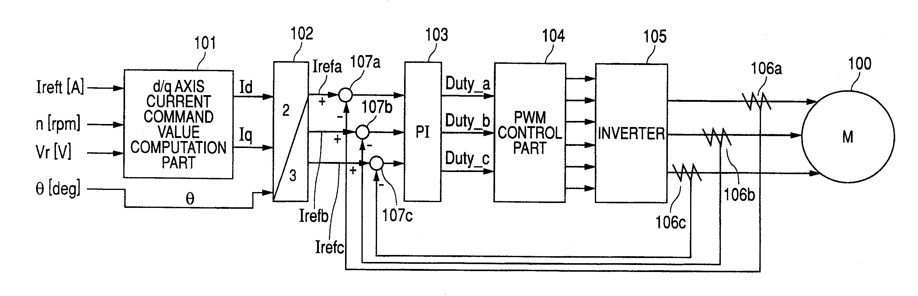
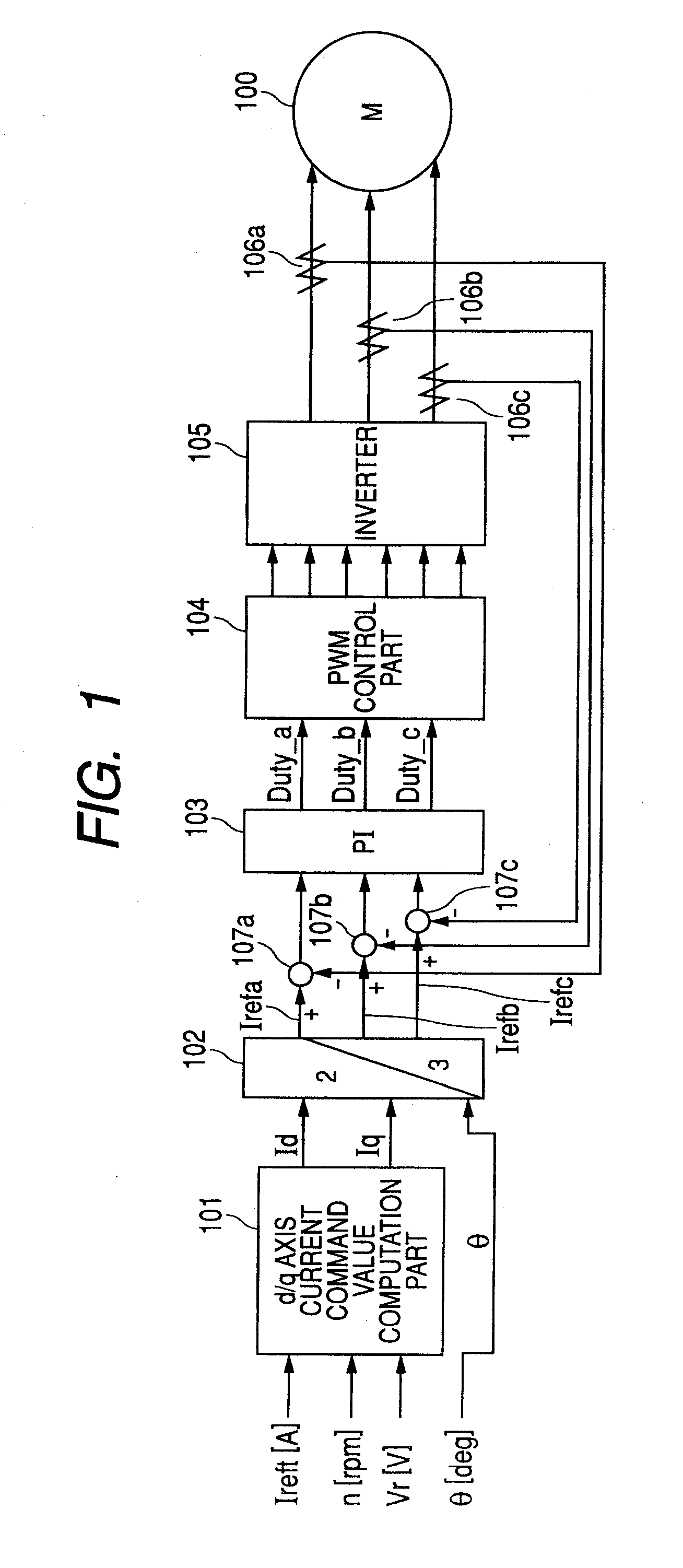
[0117] A map (data table) for defining a relation of a d axis current / q axis current, a motor rotational speed / q axis current and the amount of d axis current for flux weakening control necessary to satisfy required assistance power (required assist torque versus rotation speed characteristic) is previously created off-line using parameters such as a motor resistance value or an inductance value, an internal resistance value of a controller (control unit or ECU). Then, value and output timing of a d axis current are determined while referring to the map according to a detected motor rotational speed, a battery voltage, a current command value, etc. at the time of on-line control.

[0118] That is, FIG. 1 shows its configuration example and is constructed so as to drive a three-phase br...

Example

Second Embodiment

[0141] Next, second and third embodiments according to the seventh to eleventh aspects of the invention will be described below based on the drawings.

[0142]FIG. 16 is the whole configuration diagram showing one embodiment of the case of applying the invention to an electric power steering apparatus, and in FIG. 16, numeral 1001 is a steering wheel, and steering force generated by driver's steering operation of the steering wheel 1001 is transmitted to a steering shaft 1002 having an input shaft 1002a and an output shaft 1002b. In this steering shaft 1002, one end of the input shaft 1002a is joined to the steering wheel 1001 and the other end is joined to one end of the output shaft 1002b through a steering torque sensor 1003 acting as steering torque detection part.

[0143] Then, the steering force transmitted to the output shaft 1002b is transmitted to a lower shaft 1005 through a universal joint 1004 and is further transmitted to a pinion shaft 1007 through a uni...

Example

[0220] Next, a third embodiment of the invention will be described with reference to FIG. 28.

[0221] This third embodiment is constructed based on an m-phase so that (2mn±1)th-order harmonic components are extracted from a d axis command value and a q axis command value and amplitude compensation of the extracted (2mn±1)th-order harmonic components is individually made and then the (2mn±1)th-order harmonic components are added and thereby the first phase target current to the m-th phase target current of an m-phase brush-less motor are calculated.

[0222] That is, in the third embodiment, a target current setting part 1030 is constructed as shown in FIG. 28. In a manner similar to the second embodiment described above, in this target current setting part 1030, a steering assist current command value Iref outputted from a steering assist current command value computation part 1031 is inputted to a current command value limit part 1082 and by this current command value limit part 1082,...


PUM


Abstract

A motor drive control apparatus for controlling a motor has a main control part that performs a flux weakening control by a vector control of d-q axes and a rate-limit control part that controls a rate of change in a d axis current command value in the vector control. Further, there is provided a motor control apparatus for controlling a motor has a motor angular speed detection part that detects a motor angular speed of the motor and a motor control part having a current control system that controls the electric motor based on a motor current and a current command value. The motor control part calculate the current command value in which torque becomes constant by considering characteristics of the current control system based on a motor angular speed detected by the motor angular speed detection part.

Description

BACKGROUND OF THE INVENTION [0001] 1. Field of the Invention [0002] The present invention relates to a drive control apparatus of a motor for performing flux weakening control by vector control of d-q axes, and particularly to a motor drive control apparatus for suppressing occurrence of abnormal sound or vibration while preventing a sudden change in a motor output by controlling a rate of change (an amount of change per constant control period or unit time) in a d axis current command value in order to avoid a sudden change in a d axis current. Also, the invention relates to an electric power steering apparatus in which its motor drive control apparatus is mounted for use in motor control of electric power steering. [0003] Further, the present invention relates to an electric motor control apparatus comprising motor control part having a current control system that controls an electric motor based on a motor current and a current command value, and an electric power steering appara...

Claims


Application Information

Patent Timeline
IPC IPC(8): B62D5/04
CPCB62D5/046H02P21/0089H02P21/06
Inventor JIANG, CHUNHAOMORI, KENJISAKAGUCHI, TORUKOVUDHIKULRUNGSRI, LILIT
Owner NSK LTD
Why Eureka
Try Eureka