
Simplified rdma over ethernet and fibre channel

Inactive Publication Date: 2010-07-22
BROCADE COMMUNICATIONS SYSTEMS
View PDF2 Cites 60 Cited by
  • Summary
  • Abstract
  • Description
  • Claims
  • Application Information

AI Technical Summary

Benefits of technology

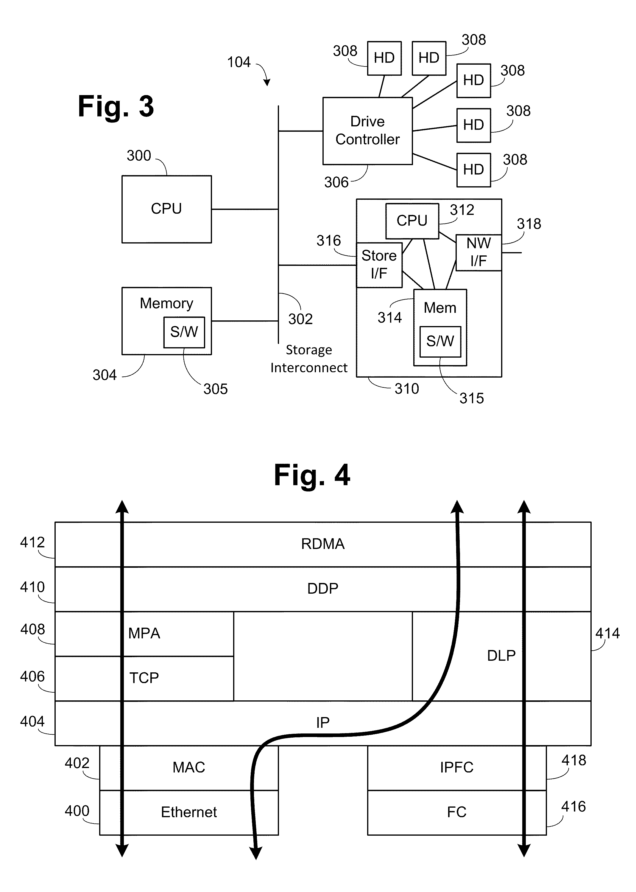
[0090]Embodiments according to the present invention utilize a new transport protocol between the IP layer and the DDP layer. Further, the embodiments all operate on a CEE-compliant layer 2 Ethernet network to allow the new transport protocol to be simplified, providing higher performance and simpler implementation. Thus the use of the new transport protocol allows a CEE-compliant layer 2 Ethernet network to provide data networking using IP, storage using FCoE and RDMA using IP and the new transport protocol, without suffering the previous performance penalties in any of these aspects.

Problems solved by technology

However, it is a fairly heavyweight protocol since TCP is designed to run over lossy networks, with long round-trip delays and significant bookkeeping and the like.
Thus iWARP is not a satisfactory solution due to cost and performance issues.
However, there seem to be no commercial implementations of SCTP.
This imposes a significant complexity on a conformant implementation.
This is because if a Stag is invalidated, and the missing segment targeted that Stag, it will encounter a “false” protection fault.
There are complexities in the iWARP specification that complicate its implementation.
These are further factors limiting the success and usefulness of iWARP.
This is however not a sufficient condition for the operation to be allowed.
One is the use of Context Addressable Memory (CAM), which is very expensive in terms of silicon size and does not scale easily to the number of connections (64K or more) required for some applications.
This adds cost in terms of on-chip memory, or attached SRAM, or consumes interconnect bus bandwidth.
This adds significant complexity in the processing stream, and additional storage requirements.
As mentioned earlier, all of these complexities have been overcome, but add cost and cause performance degradation.

Method used


Image

  • Simplified rdma over ethernet and fibre channel
  • Simplified rdma over ethernet and fibre channel
  • Simplified rdma over ethernet and fibre channel

Examples


Embodiment Construction

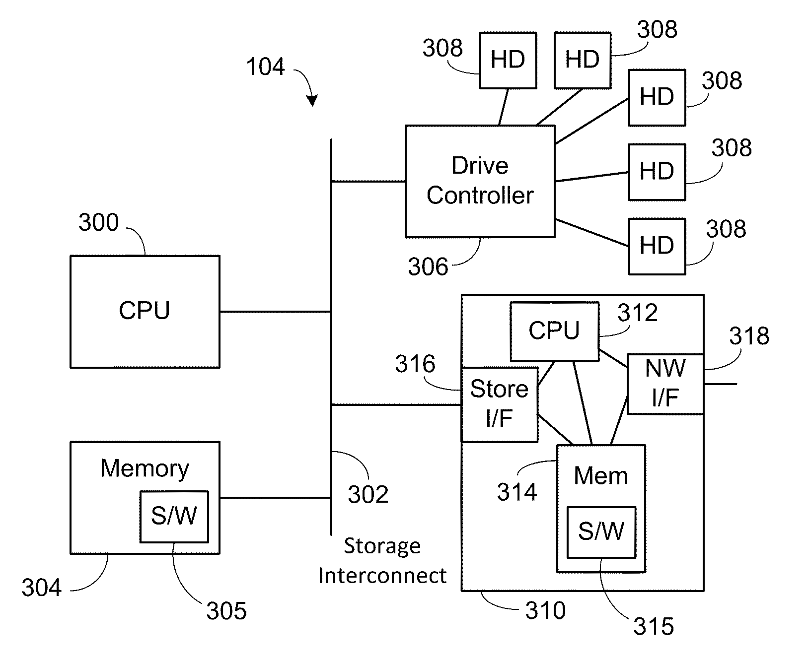
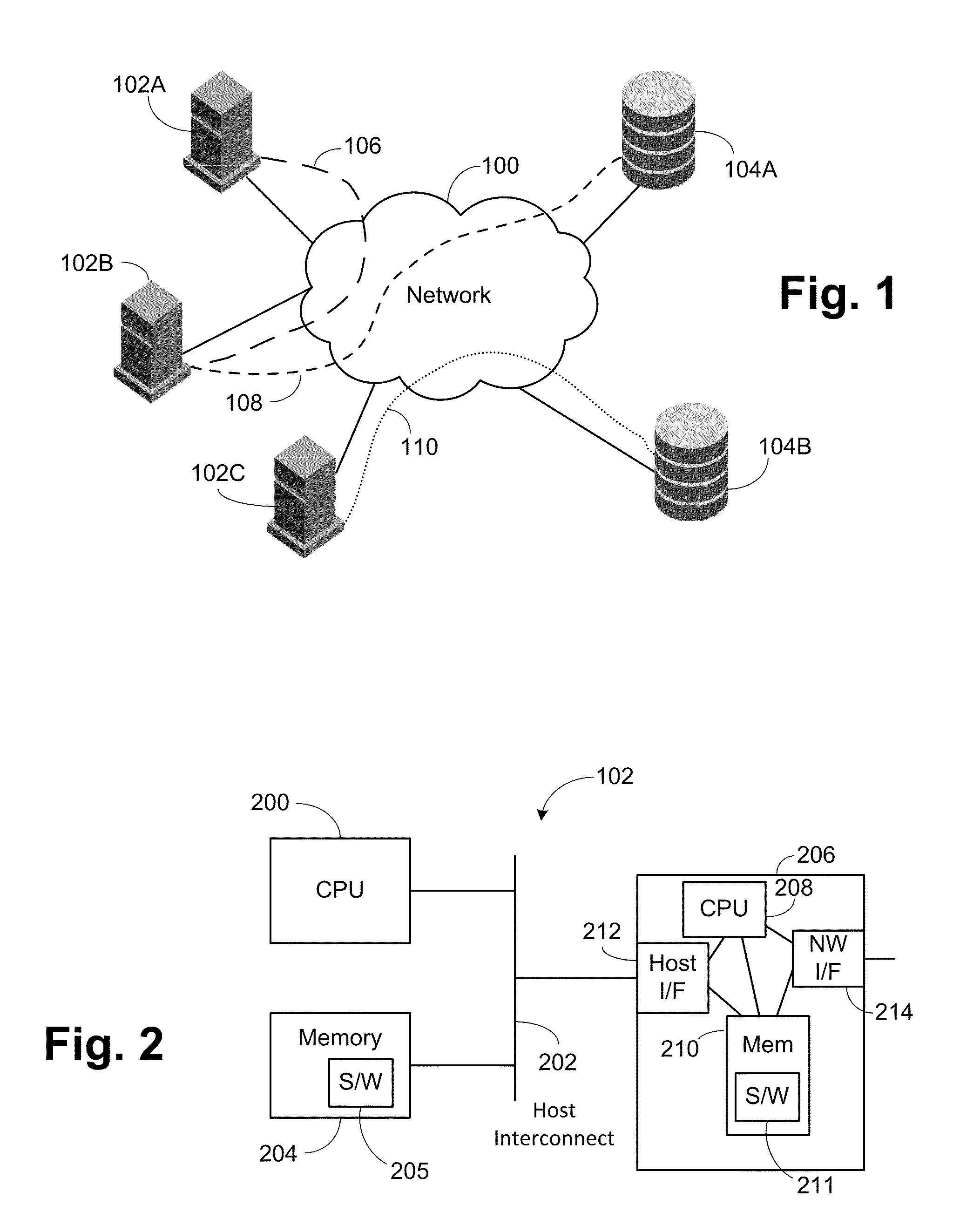
[0101]FIG. 1 illustrates a computer system according to the present invention. A network 100 connects a series of workstations or hosts 102 together and to a series of storage unit 104. Each of the hosts 102 and storage units 104 contain memory which is to be accessed directly by the other unit. A channel 106 is present between host 102A and host 102B. A channel 108 is present between host 102B and storage unit 104A. A channel 110 is present between host 102C and storage unit 104B. This is a simplified configuration for illustrating purposes and more complicated configuration can operate according to the present invention.

[0102]FIG. 2 illustrates an exemplary host 102. A CPU 200 is connected to an internal host interconnect 202. The host interconnect 202 can be items such as PCI bus, various PCI-e links or various bridge devices, as well known in the industry. The system memory 204 is connected to the host interconnect 202 to allow access by the CPU 200. A network interface card 206...


PUM


Abstract

A new transport protocol between the IP layer and the DDP layer for use with RDMA operations. The embodiments all operate on a CEE-compliant layer 2 Ethernet network to allow the new transport protocol to be simplified, providing higher performance and simpler implementation. The new protocol allows a CEE-compliant layer 2 Ethernet network to provide data networking using IP, storage using FCoE, and RDMA using IP and the new transport protocol, without suffering the previous performance penalties in any of these aspects.

Description

CROSS REFERENCE TO RELATED APPLICATIONS[0001]This application claims the benefit under 35 U.S.C. §119(e) of U.S. Provisional Patent Application Ser. No. 61 / 146,218, entitled “Protocols and Partitioning for RDMA over CEE” by Steven Wilson, Scott Kipp and Somesh Gupta, filed Jan. 21, 2009, which is hereby incorporated by reference.BACKGROUND OF THE INVENTION[0002]1. Field of the Invention[0003]The invention relates to data transfer between network devices, and more particularly to direct memory access transfers between two network devices.[0004]2. Description of the Related Art[0005]A converged network would support the following four broad classes of traffic:[0006]1) Data networking also known as IP (TCP / IP) networking,[0007]2) Storage,[0008]3) High-performance computing / clustering (HPC) and[0009]4) Management (especially sideband management traffic)[0010]HPC traffic is dependent heavily on the application and the manner in which parallelism has been extracted from the application. O...

Claims


Application Information

Patent Timeline
IPC IPC(8): H04L12/02H04L1/08G06F11/14
CPCH04L1/0072H04L1/0083H04L1/1685H04L67/1097
Inventor GUPTA, SOMESH
Owner BROCADE COMMUNICATIONS SYSTEMS
Learn More