Gas turbine seal arrangement

a technology of gas turbine and seal, applied in the direction of blade accessories, machine/engine, leakage prevention, etc., can solve the problems of increasing drag and increasing cavity temperature due to

Inactive Publication Date: 2018-08-09
SIEMENS ENERGY INC
View PDF11 Cites 6 Cited by
  • Summary
  • Abstract
  • Description
  • Claims
  • Application Information

AI Technical Summary

Benefits of technology

[0005]In accordance with an aspect of the invention, a turbine arrangement is provided comprising a rotor that rotates about a rotor axis and comprises a plurality of rotor blade segments extending radially outward, each rotor blade segment comprises an airfoil and a radially inner blade platform. A stator surrounds the rotor so as to form an annular flow path for a hot working gas, and the stator comprises a plurality of guide vane segments disposed adjacent the plurality of rotor blade segments. The plurality of guide vane segments extend radially inward, each guide vane segment comprising an airfoil and a radially inner vane platform. A seal arrangement comprises an annular face plate extending radially inward from the vane platform, a first cylindrical seal wall extending axially from an outer end of the face plate, a second cylindrical seal wall extending axially from an inner end of the face plate, an annular seal plate extending radially from an end of the second cylindrical seal wall, and an angel wing extending from the rotor and having a dista

Problems solved by technology

The static seal may be held in position by bolts having heads that extend into the disk cavity and

Method used


Image

  • Gas turbine seal arrangement
  • Gas turbine seal arrangement
  • Gas turbine seal arrangement

Examples


Embodiment Construction

[0030]In the following detailed description of the preferred embodiment, reference is made to the accompanying drawings that form a part hereof, and in which is shown by way of illustration, and not by way of limitation, a specific preferred embodiment in which the invention may be practiced. It is to be understood that other embodiments may be utilized and that changes may be made without departing from the spirit and scope of the present invention.

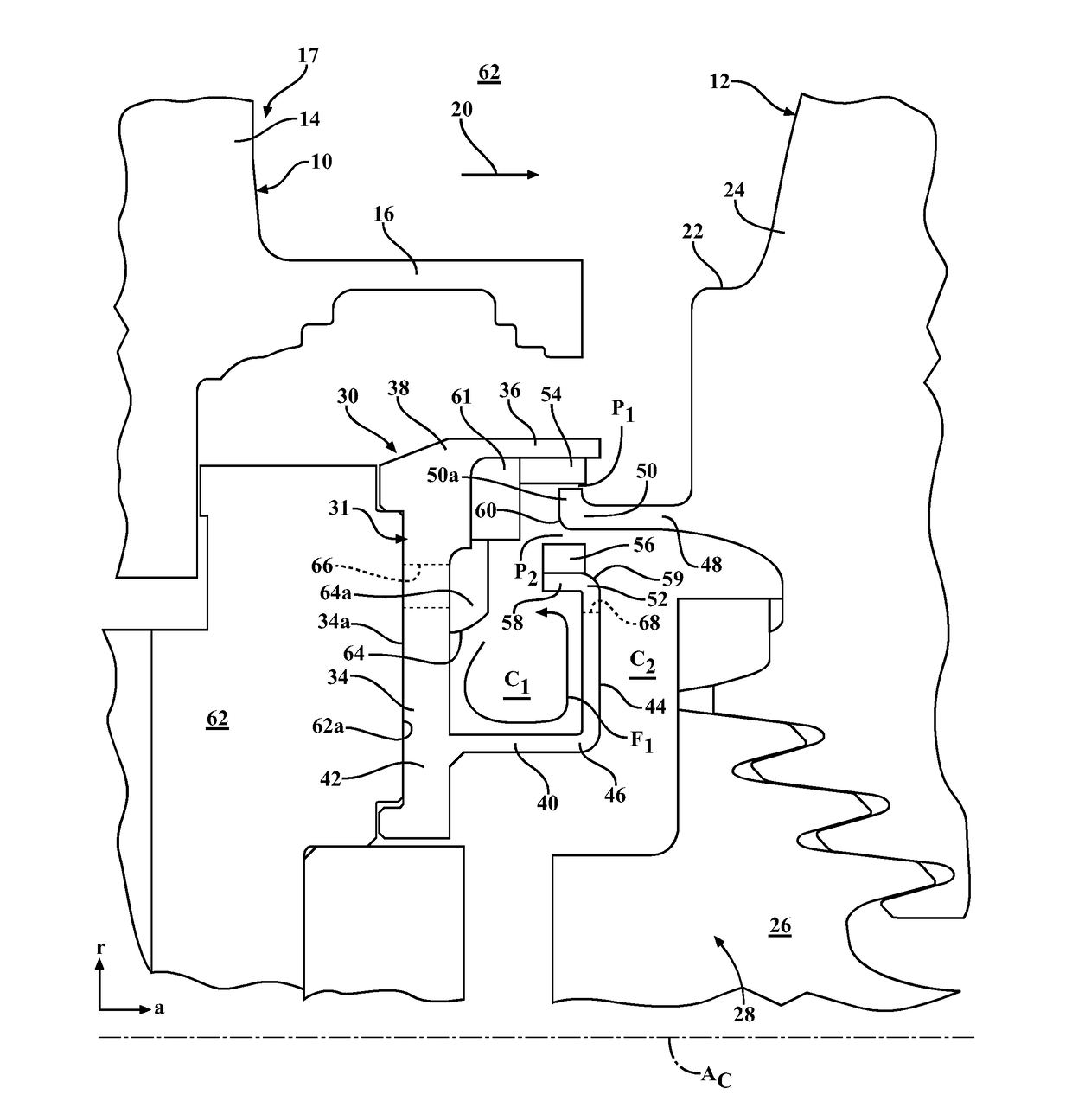
[0031]The present invention is directed to a turbine arrangement such as may comprise a gas turbine engine comprising a compressor section, a combustor section and a turbine section which are arranged adjacent to each other. In operation of the gas turbine engine, ambient air may be compressed by the compressor section, mainly provided as an input to the combustor section with one or more combustors. In the combustor section the compressed air can be mixed with liquid and / or gaseous fuel and this mixed fluid is burnt, resulting in a hot ...


PUM


Abstract

A turbine arrangement including a rotor and a stator surrounding the rotor and comprising guide vane segments, each guide vane segment comprising an airfoil and a radially inner vane platform. A seal arrangement includes a static seal inward from the inner vane platforms and having a radially extending face plate, first and second cylindrical seal walls extending from outer and inner ends of the annular face plate, an annular seal plate extending radially from the second cylindrical seal wall, and an angel wing extending between the first cylindrical seal wall and the annular seal plate to define a first annular cavity and a second annular cavity. Circumferentially spaced cut-outs define passages through the annular seal plate between the first and second annular cavities and are aligned with fasteners that attach the annular face plate to a support ring for supporting the inner vane platform.

Description

FIELD OF THE INVENTION[0001]The present invention relates to gas turbine engines and, in particular, to seal arrangements providing a seal between a hot gas flow path and a disk cavity supplied with secondary air.BACKGROUND OF THE INVENTION[0002]In a gas turbine engine, hot combustion gases are routed from a combustor to a turbine section, in which stator vanes are designed to direct the hot gases onto rotor blades resulting in rotational movement of a rotor to which the rotor blades are connected. Radially inwards and outwards of airfoils of these stator vanes and rotor blades, platforms, casing structure, or other components may be present such as to form an annular fluid passage into which the airfoils of the stator vanes and the rotor blades extend and through which the hot combustion gases pass.[0003]As the rotating rows of rotor blades and non-rotating rows of stator vanes are arranged alternately, gaps may be present between the rows of rotor blades and the rows of stator van...

Claims


Application Information

Patent Timeline
IPC IPC(8): F01D11/00F01D11/02
CPCF01D11/001F01D11/02F01D5/081F01D25/12
Inventor THAM, KOK-MUNCHEHAB, ABDULLATIF M.PILAPIL, PATRICK M.YIN, YANCAMPBELL, CHRISTIAN XAVIERLAURELLO, VINCENT PAUL
Owner SIEMENS ENERGY INC
Why Eureka
Try Eureka