Emergency Cardiac And Electrocardiogram Electrode Placement System

a technology of electrode placement and electrocardiogram, which is applied in the field of emergency cardiac and electrocardiogram electrode placement system, can solve the problems of limiting potentially interfere with diagnostic imaging, and inability to apply, so as to limit the opportunity loss of delay in diagnosis and treatment.

Active Publication Date: 2018-09-06
CB INNOVATIONS LLC
View PDF4 Cites 2 Cited by
  • Summary
  • Abstract
  • Description
  • Claims
  • Application Information

AI Technical Summary

Benefits of technology

[0011]The present invention is an emergency cardiac and electrocardiogram (ECG) electrode placement device (“EXG device”) that incorporates electrical conducting materials and elastic material into a pad that is applied to the chest wall placing the electrodes in the appropriate anatomic locations on a patient. The EXG device solves the problem of lead detachment, lead reversal, inability to apply leads due to extremes in physiology, and lack of reproducibility to measure subtle changes. The ease of use with EXG device allows for acquisition of ECGs that would not have been obtained and therefore limits the opportunity loss of delays in diagnosis and treatment.
[0012]Creation of this device will reduce the time to complete an electrocardiogram (ECG) in the pre-hospital and emergency setting, eliminate systematic error in placement and interpretation of an ECG electrode, maintain and place electrodes in the proper anatomic locations across all body types, will not delay management in critical case, maintain proper skin contact through different physiologic responses such as sweat, cold and heat, as well as through medical treatment such as CPR, be easy to train providers in application and placement of ECG electrodes, and be adaptable to scenarios where space and situations limit ECG placement.
[0013]Emergency Cardiac and Electrocardiogram (ECG) electrode placement device is a worn device that incorporates elastic electrical conducting materials and elastic material into a pad that is applied to the chest wall placing the electrodes in the appropriate anatomic locations in a rapid, reproducible, reliable fashion. It is provided in a compact, easily stored and transported form, that is applied to the chest wall with materials that have adhesive capabilities that resist moisture and conforms to the body with inherent elasticity with placement of electrodes within the pad that maintain proper anatomic ratios and locations. This device remains adherent to the body for specific lengths of time, with examples including adherence for potentially a minimum of 48 hour, but remain easily removable, while tolerating physiologic changes such as sweat and fever and medical treatment such as CPR. The device is clearly marked and designed to fit to the chest wall so that its application ensures proper placement of all electrodes. The incorporated electrical conducting materials combine together into a single cable / wire that is either directly or indirectly joined to an ECG monitoring device. The cable has adaptor capability that allows for wireless transfer of data to an ECG monitoring device obviating the need for having a bulky ECG machine in close proximity to the patient. The single cable also eliminates the need for multiple wires on a patient. Multiple wires that could potentially interfere with diagnostic imaging such as chest radiographs, or interfere with placement of emergency medical equipment such as transcutaneous cardiac pacer pads or defibrillating pad.

Problems solved by technology

The EXG device solves the problem of lead detachment, lead reversal, inability to apply leads due to extremes in physiology, and lack of reproducibility to measure subtle changes.
The ease of use with EXG device allows for acquisition of ECGs that would not have been obtained and therefore limits the opportunity loss of delays in diagnosis and treatment.
Multiple wires that could potentially interfere with diagnostic imaging such as chest radiographs, or interfere with placement of emergency medical equipment such as transcutaneous cardiac pacer pads or defibrillating pad.

Method used


Image

  • Emergency Cardiac And Electrocardiogram Electrode Placement System
  • Emergency Cardiac And Electrocardiogram Electrode Placement System
  • Emergency Cardiac And Electrocardiogram Electrode Placement System

Examples


Embodiment Construction

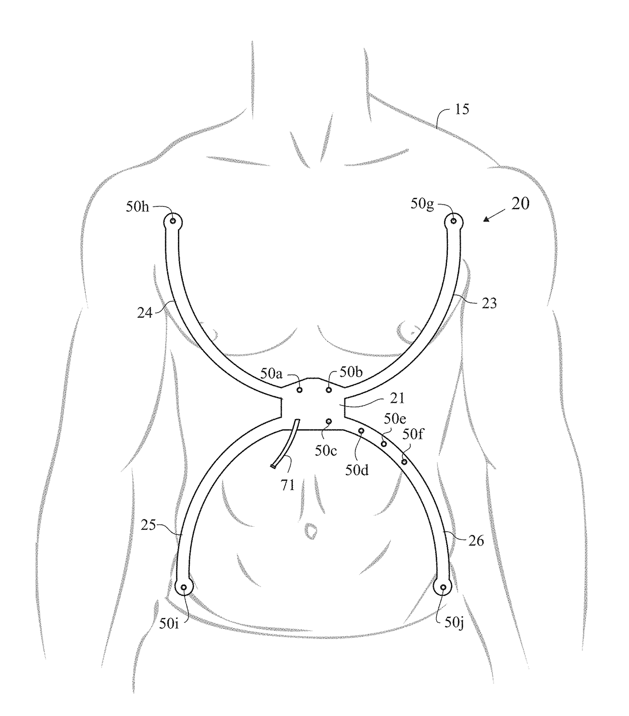
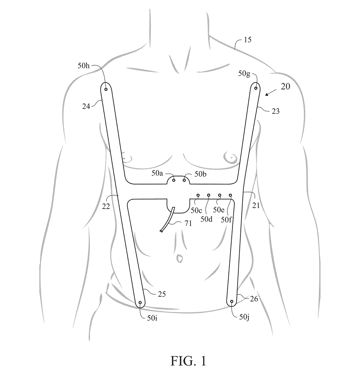
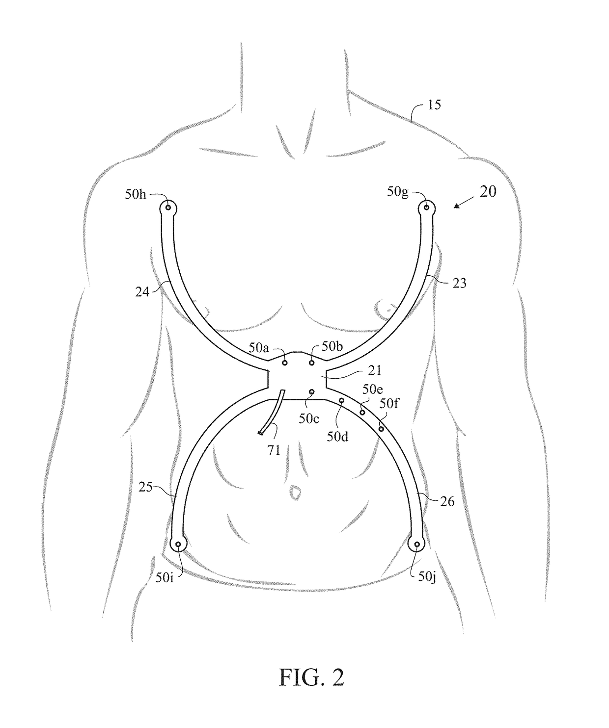
[0040]As shown in FIGS. 1 and 2, the emergency cardiac and electrocardiogram (ECG) electrode placement device (“EXG device”) 20 is a worn device that incorporates electrical conducting materials and elastic material into a pad that is applied to the chest wall placing the electrodes in the appropriate anatomic locations on a patient 15. A technician, such as an emergency responder, places the EXG device 20 on the patient 15 and connects the EXG device 20 to an ECG machine which generates an ECG.

[0041]As shown in FIGS. 1 and 2, the EXG device 20 preferably comprises a body 21, electrodes 50, printed wires or an electrical conducting flexible material 60 (not shown), and an electrode cable connector 71. The body 21 preferably comprises a center extension member 22, a first extension member 23, a second extension member 24, a third extension member 25 and a fourth extension member 26. The electrode cable connector 71 is positioned on the body 21. Each extension member 22-26 preferably ...


PUM


Abstract

An emergency cardiac and electrocardiogram (ECG) electrode placement device is disclosed herein. The emergency cardiac and electrocardiogram (ECG) electrode placement device incorporates electrical conducting materials and elastic material into a pad that is applied to a chest wall of a patient, which places multiple electrodes in the appropriate anatomic locations on the patient to quickly obtain an ECG in a pre-hospital setting.

Description

CROSS REFERENCE TO RELATED APPLICATION[0001]The Present application is a continuation-in-part application of U.S. patent application Ser. No. 15 / 853,578, filed on Dec. 22, 2017, which claims priority to U.S. Provisional Patent Application No. 62 / 465,752, filed on Mar. 1, 2017, and claims benefit of U.S. Provisional Patent Application No. 62 / 530,144, filed on Jul. 8, 2017, each of which is hereby incorporated by reference in its entirety.STATEMENT REGARDING FEDERALLY SPONSORED RESEARCH OR DEVELOPMENT[0002]Not ApplicableBACKGROUND OF THE INVENTIONField of the Invention[0003]The present invention generally relates to ECG devices.Description of the Related Art[0004]The electrocardiogram (ECG) is an essential test that provides medical professionals with essential information in the management of patients with a variety of conditions. It is not only of significant importance in the evaluation and management of patients with chest pain, but also in patients with shortness of breath, synco...

Claims


Application Information

Patent Timeline
Patent Type & Authority Applications(United States)
IPC IPC(8): A61B5/0408
CPCA61B5/04087A61B5/04085A61B5/0404A61B5/6833A61B5/0006A61B2562/063A61B2562/164A61B2562/166A61B2562/227A61B5/68335B33Y80/00A61B5/259A61B5/274A61B5/332A61B5/282
Inventor MCCLUNG, CHRISTIANDUNPHY, STEPHENRONAN, SEAN
Owner CB INNOVATIONS LLC
Why Eureka
Try Eureka