System to Pump Fluid and Control Thereof

Active Publication Date: 2018-09-06
PROJECT PHOENIX
View PDF0 Cites 20 Cited by
  • Summary
  • Abstract
  • Description
  • Claims
  • Application Information

AI Technical Summary

Benefits of technology

[0008]Preferred embodiments of the present invention provide for faster and more precise control of the fluid flow and/or pressure in systems that use a variable-speed and/or a variable-torque pump. The fluid pumping system and method of control thereof discussed below are particularly advantageous in a closed-loop type system since the faster and more precise control of the fluid flow and/or the pressure in such systems can mean smaller accumulator sizes and a reduced risk of pump cavitation than in conventional systems. In an exemplary embodiment, a fluid system includes a variable-speed and/or a variable-torque pump, at least one proportional control valve assembly, an actuator that is operated by the fluid to control a load, and a controller to concurrently establish a speed and/or torque of the pump and an opening of the at least one proportional control valve assembly. The pump includes at least two fluid drivers that provide fluid to the actuator, which can be, e.g., a fluid-actuated cylinder, a fluid-driven motor or another type of fluid-driven actuator that controls a load (e.g., a boom of an excavator, a load attached to a hydrostatic transmission, or some other equipment or device tha

Problems solved by technology

Typically, the inertia of the hydraulic pump in the above-described industrial applications makes it impractical to vary the speed of the hydraulic pump to precisely control the flow in the system.
That is, the prior art pumps in such industrial machines are not very responsive to changes in flow demand.
However, running the hydraulic pump at full speed or at some other constant speed is inefficient as it does not take into account the true energy input requirements of the system.
In addition, the flow control devices in these systems typically use hydraulic controls to operate, which can be relatively complex and require additional hydraulic fluid to function.
Because of the complexity of the hydraulic circuits and controls, these hydraulic systems are typically open-loop in that the pump draws the hydraulic fluid from a large fluid reservoir and the hy

Method used


Image

  • System to Pump Fluid and Control Thereof
  • System to Pump Fluid and Control Thereof
  • System to Pump Fluid and Control Thereof

Examples


Embodiment Construction

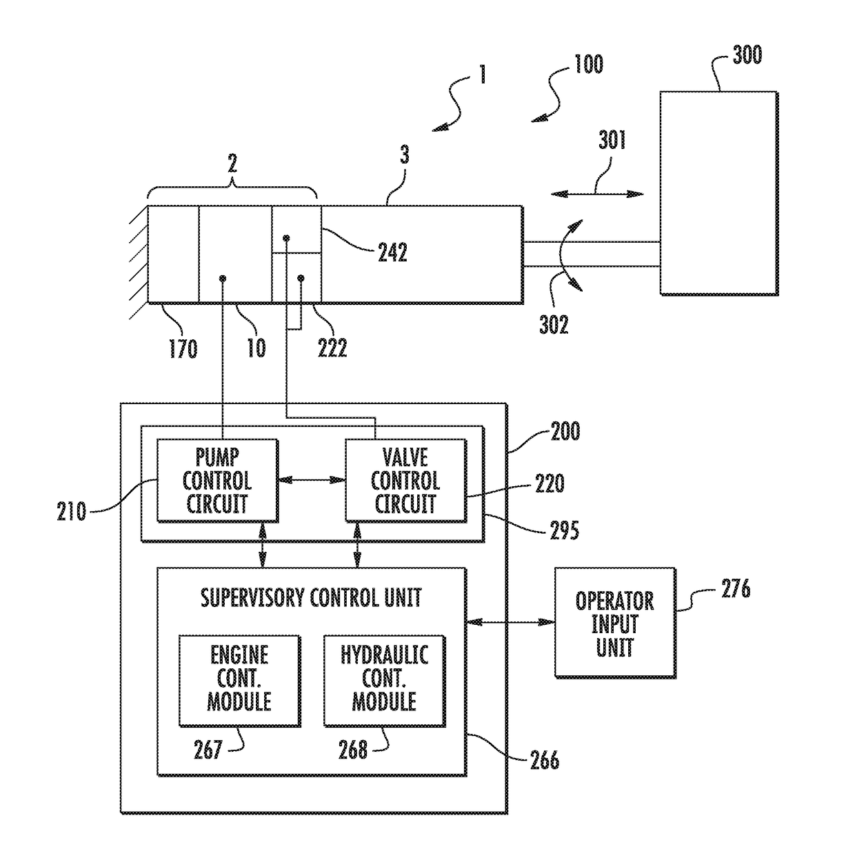
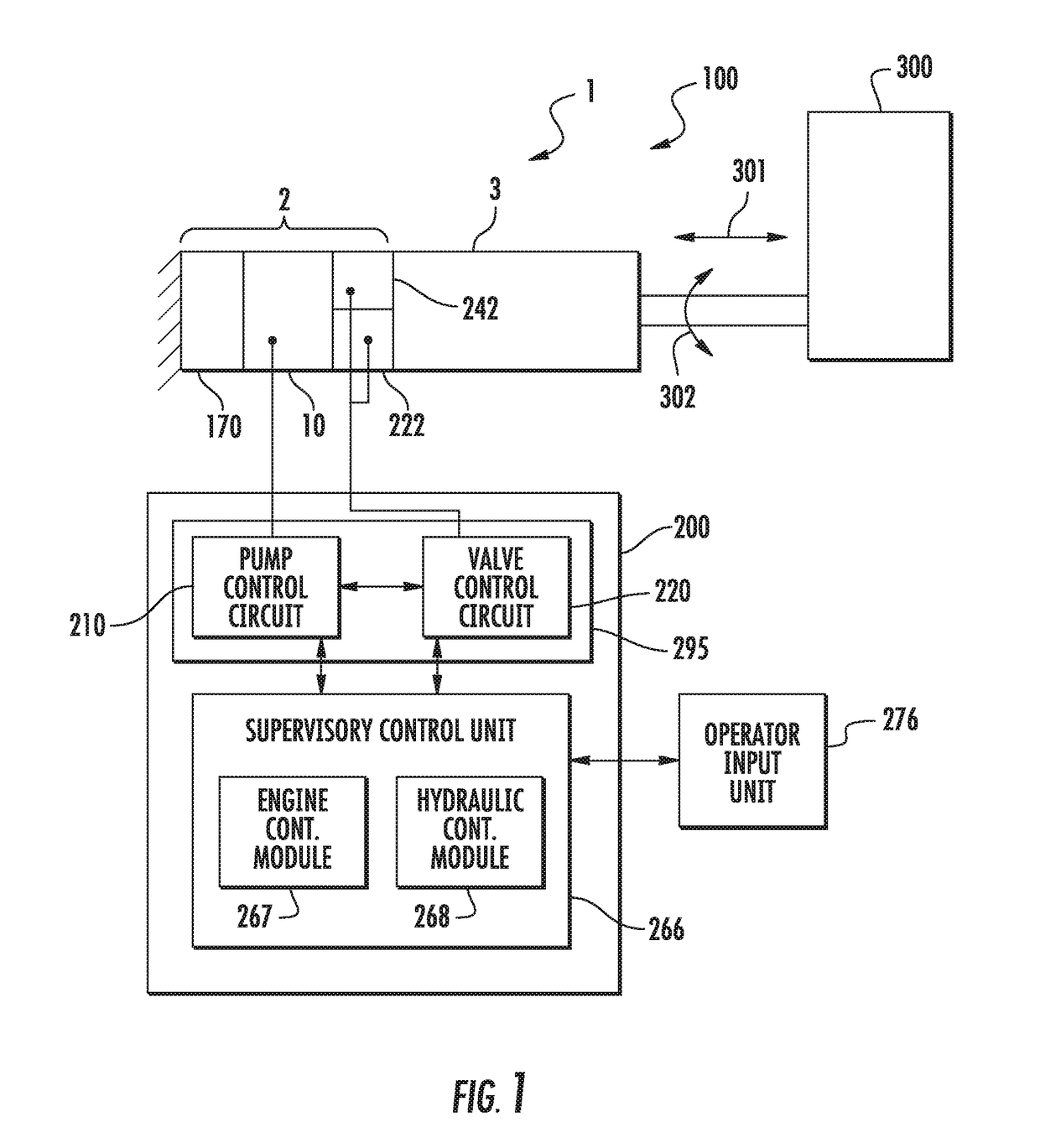
[0047]Exemplary embodiments are directed to a fluid system that includes a fluid-driven actuator assembly and a control system to operate a load. In some embodiments, the fluid-driven actuator assembly includes a fluid-driven actuator and at least one pump assembly conjoined with the fluid-driven actuator to provide fluid to operate the fluid-driven actuator. The pump assembly, which can be integrated in some embodiments, includes a pump with at least one fluid driver comprising a prime mover and a fluid displacement assembly to be driven by the prime mover such that fluid is transferred from a first port of the pump to a second port of the pump. The pump assembly also includes at least one proportional control valve assembly. In addition, in some embodiments, at least one of the pump assembly and the fluid-driven actuator can include lock valves to isolate the respective devices from the system. The fluid system also includes a controller that establishes at least one of a speed an...


PUM


Abstract

A fluid-driven actuator system includes a fluid-driven actuator and at least one proportional control valve and at least one pump connected to the fluid-driven actuator to provide fluid to operate the fluid-driven actuator. The at least one pump includes at least one fluid driver having a prime mover and a fluid displacement assembly to be driven by the prime mover such that fluid is transferred from the pump inlet to the pump outlet. The fluid-driven actuator system also includes a controller that establishes at least one of a speed and a torque of the at least one prime mover to adjust at least one of a flow in the fluid-driven system to a flow set point and a pressure in the fluid-driven actuator system to a pressure set point and concurrently establishes an opening of the at least one proportional control valve to adjust at least one of the flow to the flow set point and the pressure to the pressure set point.

Description

PRIORITY[0001]The present application is an international application claiming the benefit of priority to U.S. Provisional Application No. 62 / 213,505 filed on Sep. 2, 2015, which is incorporated herein by reference in its entirety.TECHNICAL FIELD[0002]The present invention relates generally to fluid pumping systems fluid-driven actuator assemblies and control methodologies thereof, and more particularly to fluid-driven actuator assemblies having at least one pump assembly, at least one proportional control valve assembly and a fluid-driven actuator; and control methodologies thereof in a fluid pumping system, including adjusting at least one of a flow and a pressure in the system by establishing a speed and / or torque of each prime mover in the at least one pump assembly and concurrently establishing an opening of at least one control valve in the at least one proportional control valve assembly.BACKGROUND OF THE INVENTION[0003]Fluid-driven actuator assemblies are widely used in a va...

Claims


Application Information

Patent Timeline
IPC IPC(8): F04C11/00F04C15/00F15B15/20
CPCF04C11/003F04C15/0092F04C15/0096F15B15/202F04C11/00F04C15/00F15B15/18F15B7/006F16H39/06F15B15/08F16H39/02F16H61/4008F16H61/4035F04C11/008F04C2/084F04C14/08F04C2/18F04C2270/035F04C2270/051
Inventor AFSHARI, THOMAS
Owner PROJECT PHOENIX
Why Eureka
Try Eureka