System to pump fluid and control thereof

a fluid system and fluid technology, applied in the direction of liquid fuel engines, machines/engines, servomotors, etc., can solve the problems of inefficiency of hydraulic pumping at full speed or at some other constant speed, inability to precisely control the flow in the system, and prior art pumps in such industrial machines are not very responsive to changes in flow demand, etc., to achieve faster and more precise fluid flow and/or pressure control, faster and more precise control of fluid flow and/or pressure, and the effect of smaller

Active Publication Date: 2018-09-11
PROJECT PHOENIX
View PDF106 Cites 15 Cited by
  • Summary
  • Abstract
  • Description
  • Claims
  • Application Information

AI Technical Summary

Benefits of technology

[0007]Preferred embodiments of the present invention provide for faster and more precise control of the fluid flow and / or pressure in systems that use a variable-speed and / or a variable-torque pump. The fluid pumping system and method of control thereof discussed below are particularly advantageous in a closed-loop type system since the faster and more precise control of the fluid flow and / or the pressure in such systems can mean smaller accumulator sizes and a reduced risk of pump cavitation than in conventional systems. In an exemplary embodiment, a fluid system includes a variable-speed and / or a variable-torque pump, at least one proportional control valve assembly, an actuator that is operated by the fluid to control a load, and a controller to concurrently establish a speed and / or torque of the pump and an opening of the at least one proportional control valve assembly. The pump includes at least one fluid driver that provides fluid to the actuator, which can be, e.g., a fluid-actuated cylinder, a fluid-driven motor or another type of fluid-driven actuator that controls a load (e.g., a boom of an excavator, a hydrostatic transmission, or some other equipment or device that can be operated by an actuator). As used herein, “fluid” means a liquid or a mixture of liquid and gas containing mostly liquid with respect to volume. Each fluid driver includes a prime mover and a fluid displacement assembly. The fluid displacement assembly can be driven by the prime mover such that fluid is transferred from the inlet port to the outlet port of the pump. In some embodiments, a proportional control valve assembly is disposed between the pump outlet and an inlet port of the actuator. The proportional control valve assembly can include a proportional control valve and a valve actuator. In some embodiments, the proportional control valve assembly is disposed between an outlet port of the actuator and the pump inlet. In other embodiments, the system includes two proportional control valve assemblies with one valve assembly disposed between the pump outlet and actuator inlet port and the other valve assembly disposed between the actuator outlet port and the pump inlet. The controller concurrently establishes a speed and / or a torque of the prime mover and an opening of a proportional control valve in at least one proportional control valve assembly so as to control a flow and / or a pressure in the fluid system.

Problems solved by technology

Typically, the inertia of the hydraulic pump in the above-described industrial applications makes it impractical to vary the speed of the hydraulic pump to precisely control the flow in the system.
That is, the prior art pumps in such industrial machines are not very responsive to changes in flow demand.
However, running the hydraulic pump at full speed or at some other constant speed is inefficient as it does not take into account the true energy input requirements of the system.
In addition, the flow control devices in these systems typically use hydraulic controls to operate, which can be relatively complex and require additional hydraulic fluid to function.
Because of the complexity of the hydraulic circuits and controls, these hydraulic systems are typically open-loop in that the pump draws the hydraulic fluid from a large fluid reservoir and the hydraulic fluid is sent back to the reservoir after performing work on the hydraulic actuator and after being used in the hydraulic controls.
To interconnect these parts, various additional components like connecting shafts, hoses, pipes, and / or fittings are used in a complicated manner and thus susceptible to contamination.
Moreover, these components are susceptible to damage or degradation in harsh working environments, thereby causing increased machine downtime and reduced reliability of the machine.
Thus, known systems have undesirable drawbacks with respect to complexity and reliability of the systems.

Method used


Image

  • System to pump fluid and control thereof
  • System to pump fluid and control thereof
  • System to pump fluid and control thereof

Examples


Embodiment Construction

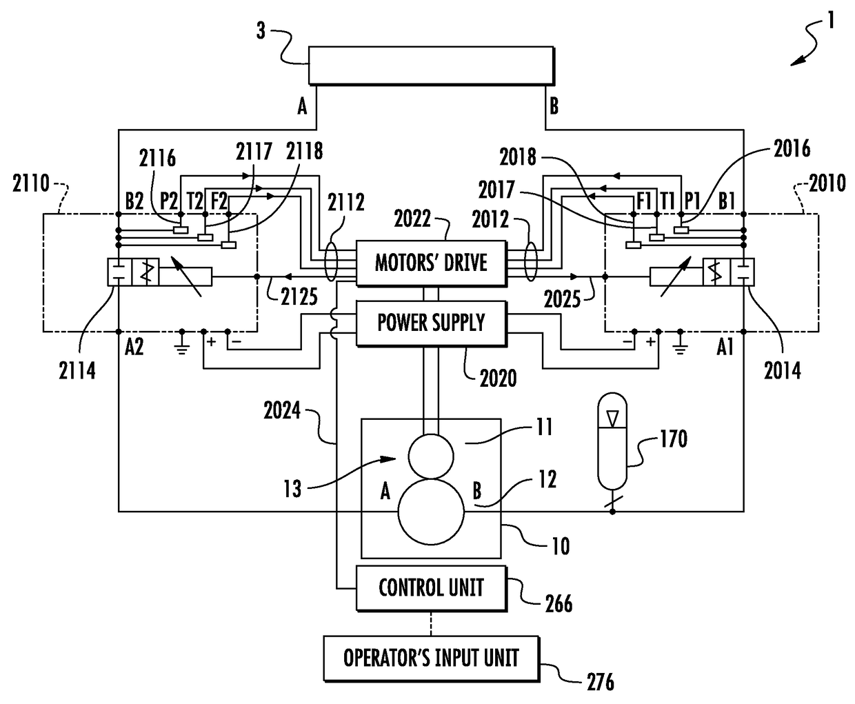
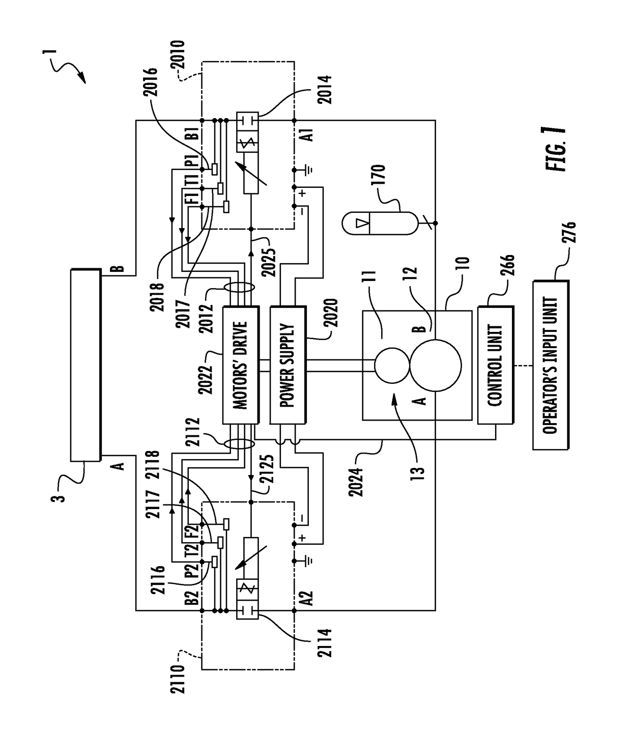
[0022]Exemplary embodiments of the present invention are directed to systems in which fluid is pumped using a variable-speed and / or a variable-torque pump and at least one proportional control valve. The operation of the pump and the at least one proportional control valve is coordinated to provide for faster and more precise control of the fluid flow and / or the pressure than in conventional systems. As discussed in further detail below various exemplary embodiments include pump configurations in which a prime mover drives a fluid displacement assembly that can have one or more fluid displacement members. In some exemplary embodiments, the fluid displacement assembly has two displacement members and the prime mover drives one fluid displacement member which in turn drives the another fluid displacement member (a driver-driven configuration). In some exemplary embodiments, the pump includes more than one fluid driver with each fluid driver having a prime mover and a fluid displacemen...


PUM


Abstract

A fluid system includes a variable-speed and / or a variable-torque pump to pump a fluid, at least one proportional control valve assembly, an actuator that is operated by the fluid to control a load, and a controller that establishes a speed and / or torque of the pump and a position of the at least one proportional control valve assembly. The pump includes at least one fluid driver that provides fluid to the actuator, which can be, e.g., a fluid-actuated cylinder, a fluid-driven motor or another type of fluid-driven actuator that controls a load. Each fluid driver includes a prime mover and a fluid displacement assembly. The fluid displacement assembly can be driven by the prime mover such that fluid is transferred from the inlet port to the outlet port of the pump.

Description

PRIORITY[0001]The present application is a continuation of International Application No. PCT / US15 / 50589 filed on Sep. 17, 2015, which claims priority to U.S. Provisional Patent Application No. 62 / 054,176 filed on Sep. 23, 2014 and U.S. Provisional Patent Application No. 62 / 212,788 filed on Sep. 1, 2015, which are incorporated herein by reference in their entirety.TECHNICAL FIELD[0002]The present invention relates generally to various systems that pump fluid and to control methodologies thereof. More particularly, the present invention relates to control of a variable speed and / or a variable torque pump with at least one fluid driver and at least one proportional control valve in the system.BACKGROUND OF THE INVENTION[0003]Systems in which a fluid is pumped can be found in a variety of applications such as heavy and industrial machines, chemical industry, food industry, medical industry, commercial applications, and residential applications to name just a few. Because the specifics o...

Claims


Application Information

Patent Timeline
Patent Type & Authority Patents(United States)
IPC IPC(8): F15B11/04F15B7/00F04C2/18F04C14/24F04C14/08F04C2/08
CPCF15B7/006F04C14/08F04C14/24F04C2/18F15B2211/785F04C2/088F04C2270/035F04C2270/051F15B2211/20515F15B2211/20538F15B2211/20561F15B2211/212F15B2211/27F15B2211/40515F15B2211/41572F15B2211/426F15B2211/455F15B2211/46F15B2211/505F15B2211/5158F15B2211/526F15B2211/632F15B2211/6313F15B2211/6343F15B2211/6651F15B2211/6653F15B2211/6654F15B2211/7053
Inventor AFSHARI, THOMAS
Owner PROJECT PHOENIX
Why Eureka
Try Eureka