Motion simulation amusement park attraction

a technology of motion simulation and amusement park, which is applied in the field of amusement park, can solve the problems of rider not being properly positioned within the ride, and rider not feeling immersed in the ride,

Active Publication Date: 2018-10-25
UNIVERSAL CITY STUDIOS LLC
View PDF5 Cites 1 Cited by
  • Summary
  • Abstract
  • Description
  • Claims
  • Application Information

AI Technical Summary

Benefits of technology

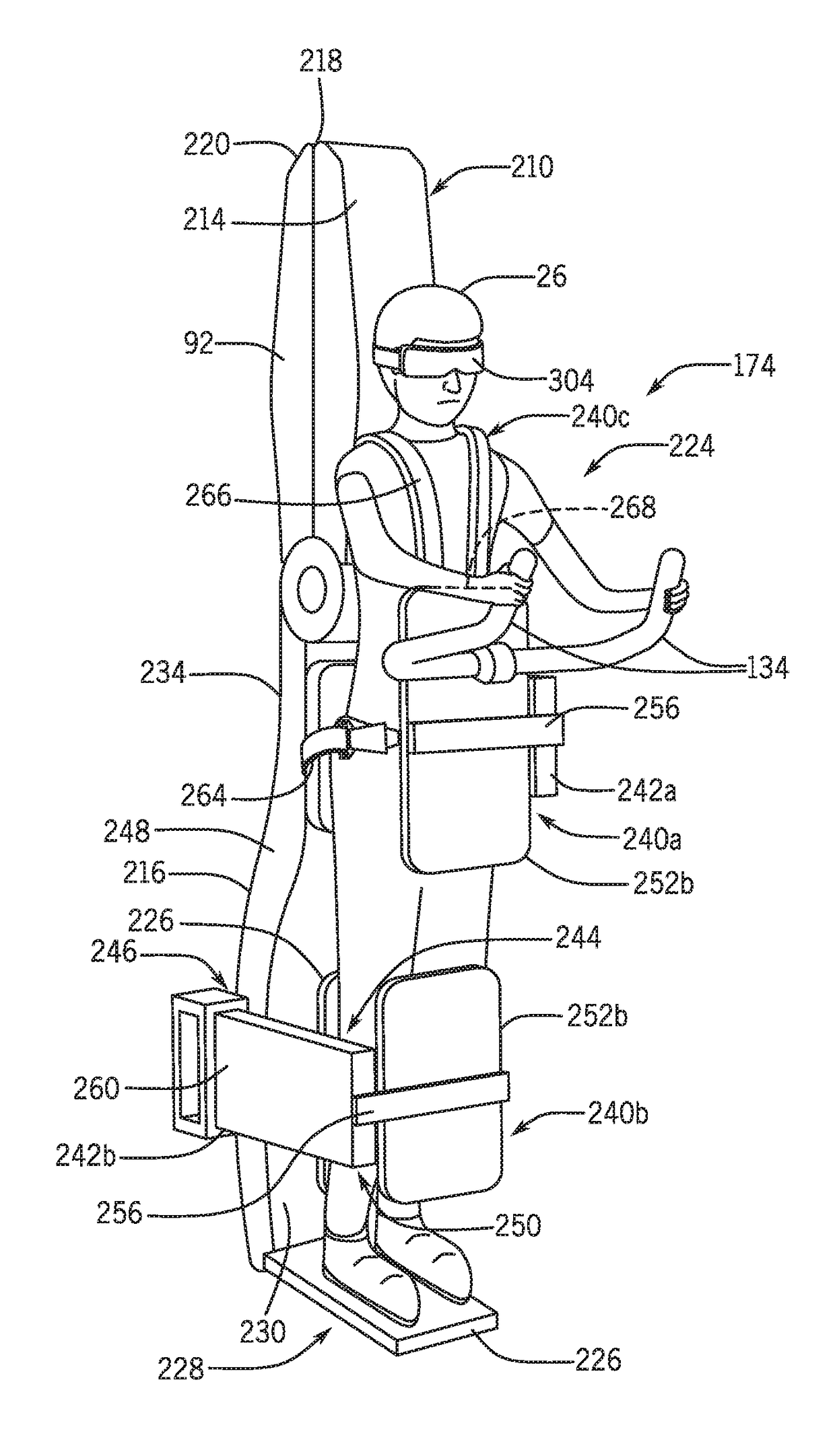
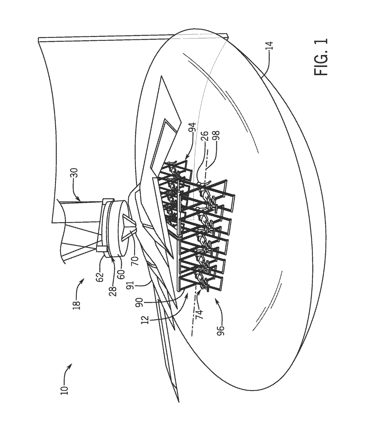
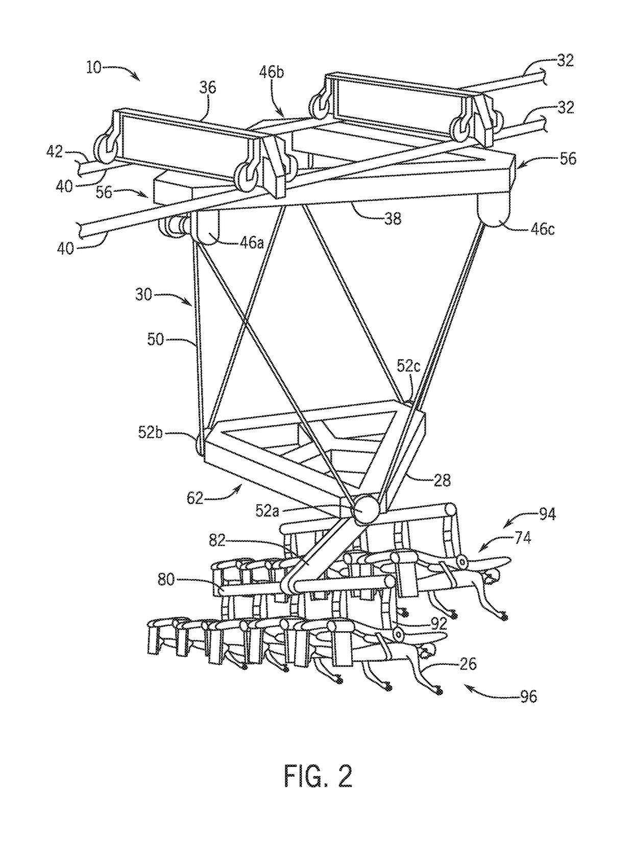
[0005]In accordance with one embodiment, a motion simulator ride assembly includes a motion base and a rider support assembly positioned beneath and coupled to the motion base. The rider support assembly includes a plurality of rider support units, each rider support unit of the one or more rider support units having an inversion table having a surface that may abut a rider. The inversion table may rotate about an axis to transition between a loading configuration and a ride configuration and the ride configuration positions the rider in a substantially facedown position. Each rider support unit also includes a restraint system that may secure the rider onto the inversion table. The restraint system includes a first moveable restraint and a second moveable restraint that are each coupled to the inversion table and the first and second moveable restraints may move relative to the surface to move the first and second movable restraints from an unrestrained configuration to a restrained configuration. The motion simulator ride assembly also includes a display screen that may project a simulated environment. The display screen is positioned below the motion base.
[0006]In accordance with another embodiment, a rider support assembly includes one or more rider support units, each rider support unit of the one or more rider support units having a moveable base having a first end, a second end, and a surface extending between the first end and the second end. The moveable base may support and position a rider substantially horizontally in a facedown position. Each of the one or more rider support units also includes a restraint system having a torso restraint having a rotating restraint extending from the moveable base and that may move relative to the surface from an unrestrained configuration to a restrained configuration and a leg restraint positioned adjacent to the second end and having a fixed member and a moveable member spaced apart from the fixed member. The moveable member may move relative to the fixed member to move the leg restraint from an unrestrained configuration to a restrained configuration.

Problems solved by technology

However, it is now recognized that regardless of such enhancements to these passenger vehicle rides, the rider in the passenger vehicle may not feel immersed in the ride.
However, the rider may not be properly positioned within the ride to fully experience movements simulated by the ride.

Method used


Image

  • Motion simulation amusement park attraction
  • Motion simulation amusement park attraction
  • Motion simulation amusement park attraction

Examples


Embodiment Construction

[0020]One or more specific embodiments of the present disclosure will be described below. In an effort to provide a concise description of these embodiments, all features of an actual implementation may not be described in the specification. It should be appreciated that in the development of any such actual implementation, as in any engineering or design project, numerous implementation-specific decisions must be made to achieve the developers' specific goals, such as compliance with system-related and business-related constraints, which may vary from one implementation to another. Moreover, it should be appreciated that such a development effort might be complex and time consuming, but would nevertheless be a routine undertaking of design, fabrication, and manufacture for those of ordinary skill having the benefit of this disclosure.

[0021]When introducing elements of various embodiments of the present invention, the articles “a,”“an,”“the,” and “said” are intended to mean that the...


PUM


Abstract

A motion simulator ride assembly includes a motion base and a rider support assembly positioned beneath and coupled to the motion base. The rider support assembly includes a plurality of rider support units, each rider support unit of the one or more rider support units having an inversion table having a surface that may abut a rider. The inversion table may rotate about an axis to transition between a loading configuration and a ride configuration and the ride configuration positions the rider in a substantially facedown position. Each rider support unit also includes a restraint system that may secure the rider onto the inversion table. The restraint system includes a first moveable restraint and a second moveable restraint that are each coupled to the inversion table and the first and second moveable restraints may move relative to the surface to move the first and second movable restraints from an unrestrained configuration to a restrained configuration. The motion simulator ride assembly also includes a display screen that may project a simulated environment. The display screen is positioned below the motion base.

Description

CROSS-REFERENCE TO RELATED APPLICATIONS[0001]This application claims the benefit of U.S. Provisional Application No. 62 / 489,895, filed Apr. 25, 2017, which is hereby incorporated by reference in its entirety.BACKGROUND[0002]The present disclosure relates generally to the field of amusement parks. More particularly, embodiments of the present disclosure relate to systems and methods for amusement park rides with motion simulation.[0003]Various amusement rides have been created to provide passengers with unique motion and visual experiences. In one example, roller coasters and theme rides can be implemented with multi-passenger vehicles that travel along a fixed path. In addition to the excitement created by the speed or change in direction of the vehicles as they move along the path, the vehicles themselves may generate special effects, e.g., sound and / or motion effects. Although a repeat rider may be familiar with the general path of the ride, the special effects may create interest...

Claims


Application Information

Patent Timeline
Patent Type & Authority Applications(United States)
IPC IPC(8): A63G31/16A63G31/14A63G21/20G06T19/00
CPCA63G31/16A63G31/14A63G21/20G06T19/006A63G1/00A63G7/00A63G29/00A63G29/02A63G31/08A63J3/00
Inventor FREEDMAN, DANIELWHITE, NATHANAEL G.STENZLER, PAULA
Owner UNIVERSAL CITY STUDIOS LLC
Why Eureka
Try Eureka