
Flexible rack for linear free-run damper

Inactive Publication Date: 2018-11-01
ILLINOIS TOOL WORKS INC
View PDF4 Cites 1 Cited by
  • Summary
  • Abstract
  • Description
  • Claims
  • Application Information

AI Technical Summary

Benefits of technology

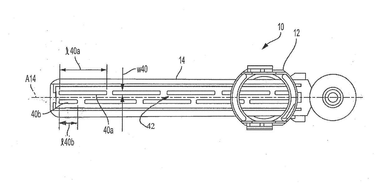
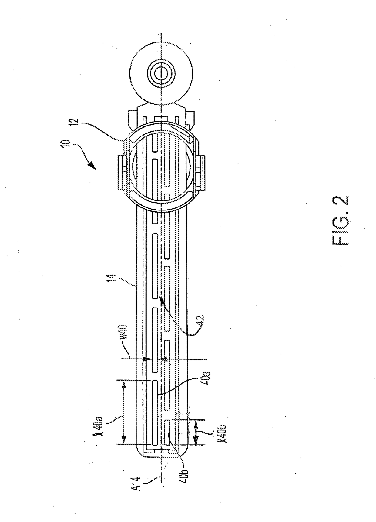
The invention is a linear damper for a device or system that can control the movement of an object. It includes a housing, a rotor, and a pinion, which work together to move a rack with teeth that engage with the pinion. The rack has elongated slots that are aligned with the movement direction of the pinion. The damper housing can be positioned at either end of the rack and can be adjacent to a bridge formed by the spaces between adjacent slots. The damper can control the movement of the object smoothly and accurately.

Problems solved by technology

As the damper moves along the rack, the pinion engages the rack gear teeth and rotates the rotor within the fluid, thus dampening movement of the pinion.
Imprecise engagement between the rack and the pinion may generate unacceptable noises; for example, unless the rotary damper is constrained, it may rattle when subject to vibration.
One drawback with maintaining such a stiff or inflexible rack is that the nip of the rotor can rub on the floor of the rack.
In some cases, the frictional forces due to rubbing are so high that the rotor will bind on the floor of the rack.
In that known racks used in this damper are solid and inflexible, any dimensional variation can result in excessive normal load, also referred to as binding.
The resulting friction is high and fluctuates depending on the dimensional stack-up of the components, as well as settling of overall height of damper assembly over time.
This in turn causes even more dimensional and force variations.

Method used


Image

  • Flexible rack for linear free-run damper
  • Flexible rack for linear free-run damper
  • Flexible rack for linear free-run damper

Examples


Embodiment Construction

[0028]While the present invention is susceptible of embodiment in various forms, there is shown in the drawings and will hereinafter be described a presently preferred embodiment with the understanding that the present disclosure is to be considered an exemplification of the invention and is not intended to limit the invention to the specific embodiment illustrated.

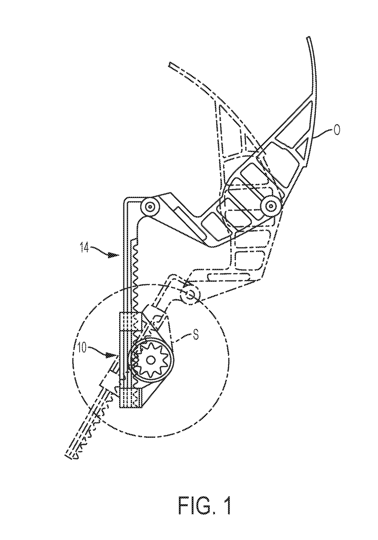
[0029]Referring to the figures and in particular to FIG. 1, there is shown one typical use for a damper assembly 10 that is used to dampen the movement of a panel O, such as a glove compartment door, for an automobile. The damper assembly 10 includes a damper, illustrated generally at 12, and a rack 14. The damper 12 includes a carriage 16, and a pinion 18 mounted to a rotor 20. The rotor 20 is in a fluid, such as a silicone fluid to dampen movement of the rotor 20. Those skilled in the art will recognize the configuration of such a damper 12. A lower portion as indicated at 22 of the damper 12 is defined by a depending p...


PUM


Abstract

A linear damper includes a damper housing, a rotor (20) positioned in the damper housing and a pinion (18) operably mounted to the rotor (20). A linear rack (14) has a base (32) and at least one upstanding side wall (30, 34), generally perpendicular to the base (32). The rack (14) has teeth (26) thereon for engagement with the pinion (18) as the pinion (18) moves along the rack (14) in a direction. The rack (14) has a plurality of elongated slots (40) formed therein in the direction of movement of the pinion (18) along the rack (14).

Description

CROSS-REFERENCE TO RELATED APPLICATION DATA[0001]This application claims the benefit of and priority to Provisional U.S. Patent Application Ser. No. 62 / 265,153, filed Dec. 9, 2015, the disclosure of which is incorporated herein in its entirety.BACKGROUND[0002]Dampening devices are used to dampen the movement of an object, such as a pivotally supported structural part. One example of such a pivotally supported part is the closure of a door of a glove compartment in an automobile. To dampen the movement of the door, rotary dampers and rack gears or racks are often used. Conventional rotary dampers include a rotor which is rotatably mounted in a housing. A braking fluid such as a silicone oil between the rotor and the housing provides for a dampening action when the rotor is being rotated in the housing. A pinion is mounted on the rotor shaft and engages the teeth of the rack. As the damper moves along the rack, the pinion engages the rack gear teeth and rotates the rotor within the fl...

Claims


Application Information

Patent Timeline
IPC IPC(8): E05F3/14
CPCE05F3/14E05Y2201/254E05Y2201/264F16F9/12E05F5/02E05Y2201/716E05Y2201/722
Inventor CHOW, HIN B.
Owner ILLINOIS TOOL WORKS INC
Learn More