Fixing device

Active Publication Date: 2018-12-06
CANON KK
View PDF1 Cites 0 Cited by
  • Summary
  • Abstract
  • Description
  • Claims
  • Application Information

AI Technical Summary

Benefits of technology

[0005]A principal object of the present invention is to provide a fixing device capable of suppressing d

Problems solved by technology

In the case where the power is not transmitted to the fixing member during drive of the motor due to failure or the like of the gears although the motor is normally driven, there is a possibility that the fixing member is not rotated and is deformed by being increased in temperature and thus an image defect occurs.
However, in the

Method used


Image

  • Fixing device
  • Fixing device
  • Fixing device

Examples


first embodiment

(Image Forming Apparatus)

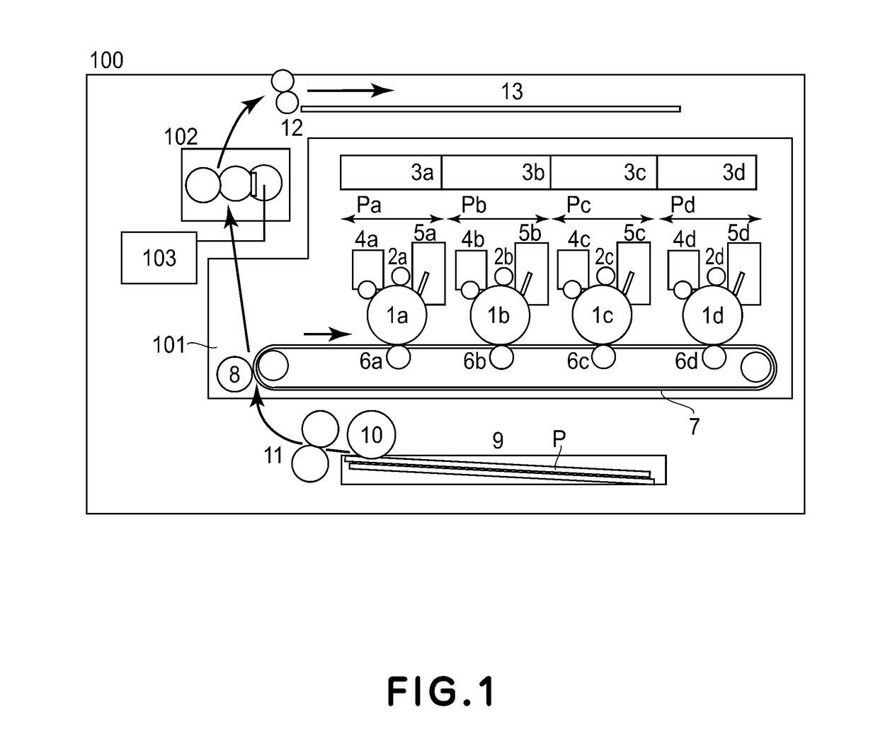
[0024]FIG. 1 is a sectional view showing a schematic structure of an image forming apparatus (full-color printer) 100 in which a fixing device according to this embodiment is mounted. In the image forming apparatus 100, an image forming portion 101 includes four image forming stations Pa, Pb, Pc and Pd for yellow, cyan, magenta and black, respectively. The image forming stations include photosensitive members 1a, 1b, 1c and 1d as image bearing members, charging members 2a, 2b, 2c and 2d, laser scanners 3a, 3b, 3c and 3d, and developing devices 4a, 4b, 4c and 4d, respectively.

[0025]The image forming stations further include cleaners 5a, 5b, 5c and 5d for cleaning the photosensitive members and transfer members 6a, 6b, 6c and 6d, respectively. Further, the image forming stations include a belt 7, as an intermediary transfer member, for feeding toner images transferred from the photosensitive members while carrying the toner images, and a secondary transfer mem...

second embodiment

[0067]This embodiment is basically pursuant to First Embodiment, but as shown in FIG. 8, is different from First Embodiment in that a sequence SS6 is added in the case of “NO” of the sequence S6. FIG. 8 is a flowchart showing a rotation detecting sequence in this embodiment. In the case of “NO” of the sequence S6, the sequence SS6 in which the temperature lowering rate is calculated as the temperature lowering information and is compared with the threshold X is carried out. As a result, a detecting speed during the normal rotation can be improved.

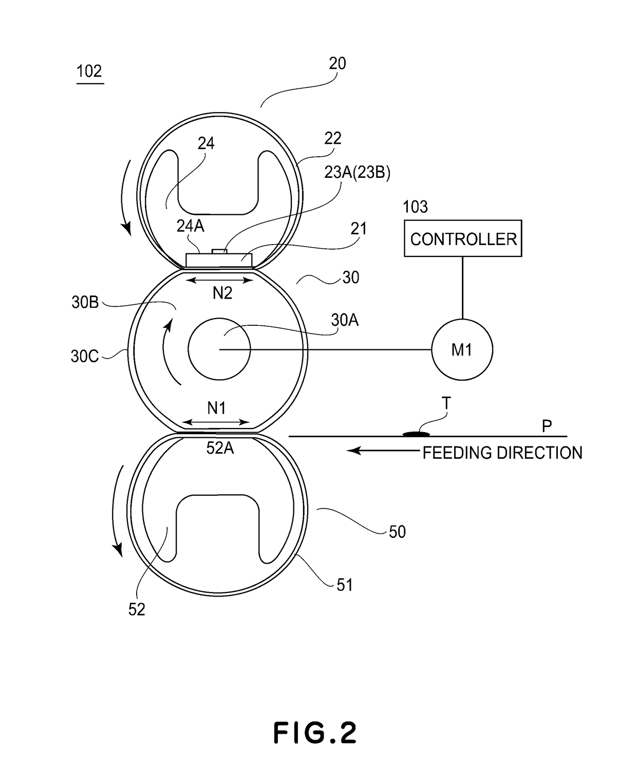
[0068]That is, in this embodiment, when the temperature T2.5 is detected, the thermistor is not on stand-by for a lapse of the predetermined time (2.5 sec), but the detection of the rotation of the fixing member corresponding to the energization to the motor is carried out in real time. That is, at a current thermistor temperature, the temperature lowering rate is calculated in real time. Then, even before the lapse of 2.5 sec, in a stage i...

third embodiment

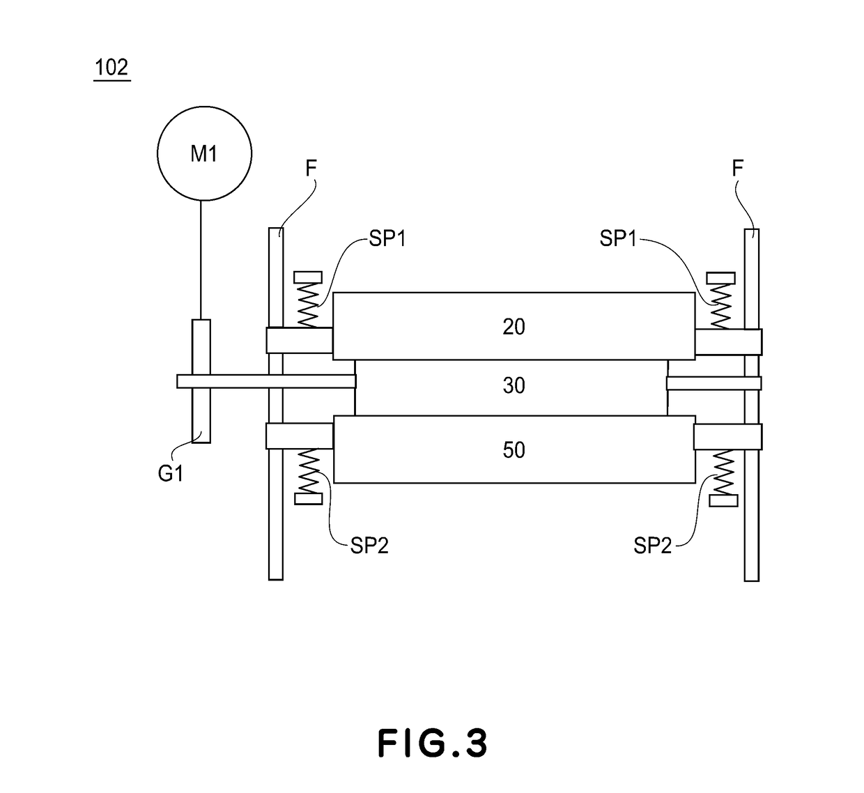
[0072]This embodiment is basically pursuant to First Embodiment, but as shown in FIG. 9, is different from First Embodiment in that a mechanism for spacing and contacting between the motor M1 and the gear G1 (i.e., a mechanism for shutting off and connecting drive transmission from the motor M1 to the fixing roller 30 as the fixing member) is provided in the fixing device. Further, in this embodiment, as shown in FIG. 10, before the sequence S1, a sequence PS1 in which a gear G2 for connecting a gear G3 and the gear G1 is inserted between the gears G1 and G3 is carried out.

[0073]Parts (a) and (b) of FIG. 9 are front views each showing a schematic structure of the fixing device 102 as seen from an upstream side with respect to the recording material feeding direction. When a recovering process from sheet (paper) jam during printing or the like process is carried out, there is a need to discharge the recording material P nipped in the fixing nip N1, but for the purpose of alleviating ...


PUM


Abstract

A fixing device includes a first rotatable member, a second rotatable member, a heat generating member, a temperature detecting member configured to detect a temperature of the heat generating member, a motor configured to drive the first rotatable member or the second rotatable member, and a controller configured to control the fixing device. The controller causes the motor to rotate in a state in which predetermined electric power is supplied to the heat generating member and then supply of electric power to the heat generating member is stopped. On the basis of a change amount of a detected temperature of the temperature detecting member during rotation of the motor, the controller detects a rotational state of the first rotatable member or the second rotatable member.

Description

FIELD OF THE INVENTION AND RELATED ART[0001]The present invention relates to a fixing device for use with an image forming apparatus, such as a copying machine or a printer, employing an image forming process of an electrophotographic type, for example.[0002]In the image forming apparatus of the electrophotographic type, a toner image transferred on a recording material is fixed on the recording material under application of heat and pressure exerted by a fixing member. It has been widely known that a rotatable member is used as the fixing member, and drive of the fixing member is carried out in many cases by a constitution in which power of a motor is transmitted using gears. In the case where the power is not transmitted to the fixing member during drive of the motor due to failure or the like of the gears although the motor is normally driven, there is a possibility that the fixing member is not rotated and is deformed by being increased in temperature and thus an image defect oc...

Claims


Application Information

Patent Timeline
IPC IPC(8): G03G15/20G03G15/00
CPCG03G15/2053G03G15/2039G03G15/2078G03G15/2028G03G15/657G03G15/5008G03G2215/2035
Inventor NAKAMOTO, ATSUSHIMITANI, TAKANORINISHIDA, SATOSHITAKEDA, ISAMUOMATA, MASAHITOMINAMISHIMA, YASUHITO
Owner CANON KK
Why Eureka
Try Eureka